Electric tensioner, twister and tension control method
A technology of tension control and tensioner, which is applied in the field of twisting machine, tension control and electric tensioner, can solve the problems of complex operation and maintenance, fiber damage, etc., and achieve the effect of large adjustment range, reduced strength loss and reduced wear
- Summary
- Abstract
- Description
- Claims
- Application Information
AI Technical Summary
Problems solved by technology
Method used
Image

Examples
Embodiment 1
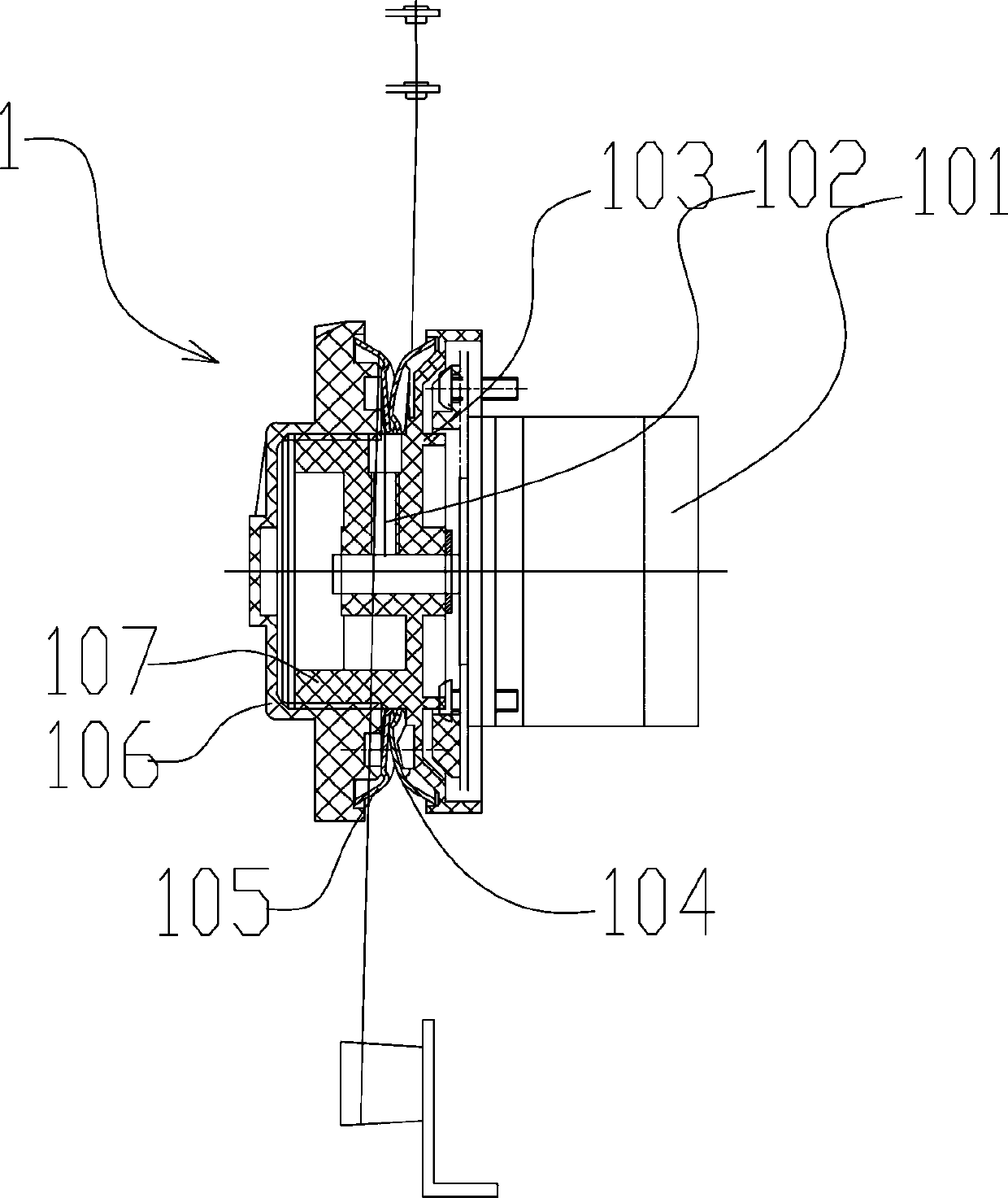
[0030] Such as image 3 Among them, an electric tensioner includes a tension motor 101 and a yarn guide disc, the tension motor 101 is fixedly connected to the frame 9, the tension motor 101 is fixedly connected to the yarn guide disc, and the yarn 2 bypasses the yarn guide disc. Yarn 2 in this example refers to the outer yarn.
[0031] In a preferred solution, in the yarn guide disc, the inner disc seat 103 is fixedly connected to the output shaft of the tension motor 101, and the inner disc seat 103 is fixedly provided with an inner flower disc 104; specifically, the threaded section 107 of the inner disc seat 103 is sleeved on On the output shaft of tension motor 101, fix by fastening screw 102. The threaded section 107 is provided with external threads;
[0032] The outer disc base 106 is fixedly connected with the inner disc base 103 , and the outer disc base 106 is fixedly provided with an outer flower disc 105 . The outer disc seat 106 is fixedly connected with the t...
Embodiment 2
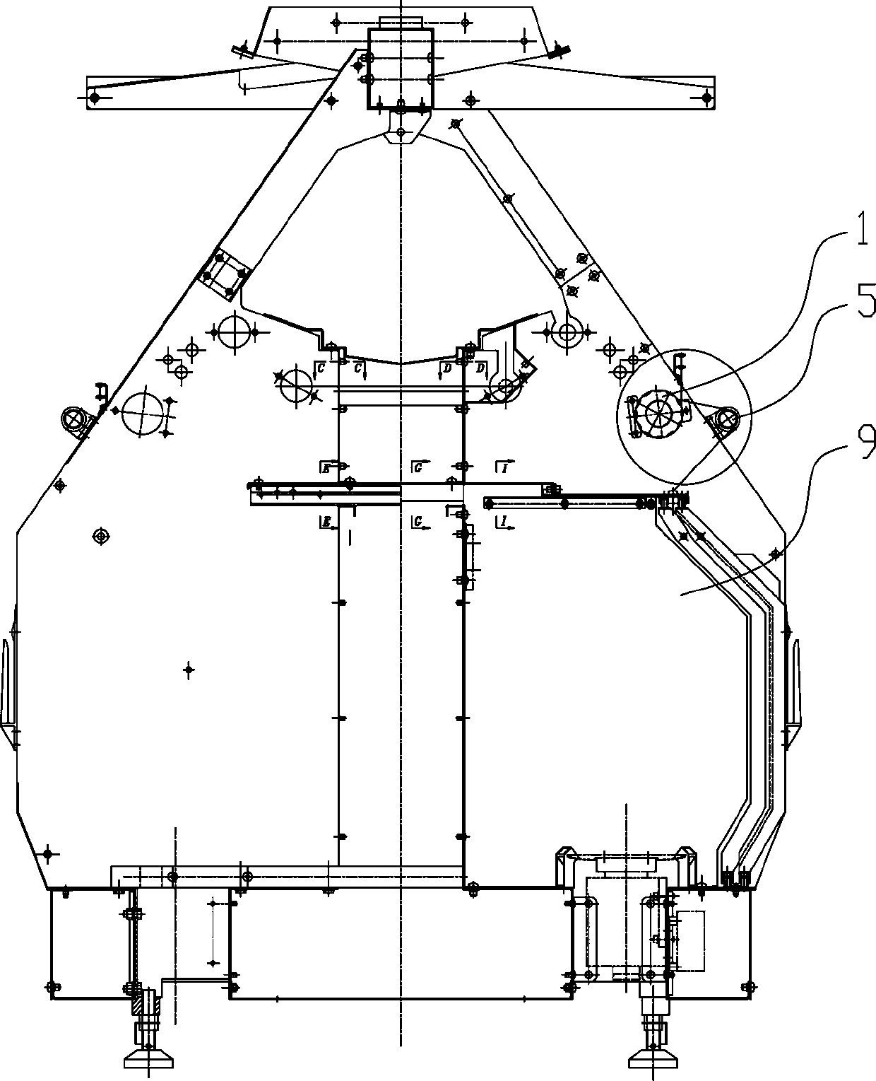
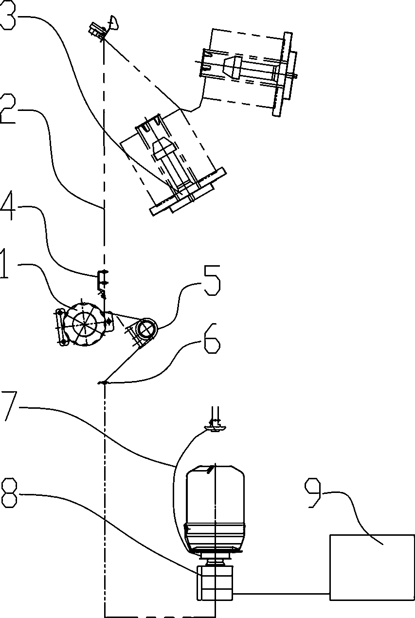
[0036] Such as figure 1 , 2 Among them, on the basis of Embodiment 1, a twisting machine using the above-mentioned electric tensioner is provided with an electric tensioner between the creel 3 and the spindle 8 of the twisting machine.
[0037] In a preferred solution, only one electric tensioner is provided between the creel 3 and the spindle 8 of the twisting machine as the outer yarn tension control component.
[0038] In a preferred solution, with reference to the moving direction of the yarn 2, a guide tube 4 is provided upstream of the electric tensioner 1, and a guide wheel 5 is provided downstream;
[0039] Such as image 3 As shown in , there is a distance between the guide tube 4 and the guide wheel 5 along the axial direction of the electric tensioner 1, so that the yarn 2 contacts the inner flower disc 104 when entering the yarn guide disc of the electric tensioner 1, and leaves The yarn guide disc of the electric tensioner 1 is in contact with the outer flower ...
Embodiment 3
[0043] On the basis of embodiment 1,2, a kind of tension control method that is used for above-mentioned twisting machine comprises the following steps:
[0044] s1. When starting, the control device controls the electric tensioner 1 to rotate along the yarn feeding direction for a period of time T1; this structure can greatly reduce the strong damage caused by static friction. It is also one of the important reasons why the structure of the present invention can reduce the strength loss. T1 is 0.5-5 seconds, preferably 2-3 seconds.
[0045] s2. The control device controls the electric tensioner 1 to run for a period of time T2 in a damping manner; T2 takes 5 to 300 seconds, preferably 30 seconds.
[0046] During the operation of the power generation mode, the damping of the electric tensioner 1 is controlled by the damping adjustment circuit; the control device outputs PWM output pulse width modulation PWM signal to the damping adjustment circuit, and the damping adjustment c...
PUM
 Abstract
Description
Claims
Application Information
 - R&D
- Intellectual Property
- Life Sciences
- Materials
- Tech Scout
- Unparalleled Data Quality
- Higher Quality Content
- 60% Fewer Hallucinations
Browse by: Latest US Patents, China's latest patents, Technical Efficacy Thesaurus, Application Domain, Technology Topic, Popular Technical Reports.
© 2025 PatSnap. All rights reserved.Legal|Privacy policy|Modern Slavery Act Transparency Statement|Sitemap|About US| Contact US: help@patsnap.com