Integrated detection equipment and detection method for mine rock mass mining damage range

A technology for mining damage and detection equipment, which is used in surveying, earth-moving drilling, wellbore/well components, etc. It can solve the problem that numerical simulation cannot reflect the field situation well, the applicability of empirical formulas is poor, and the blindness of empirical formulas is large, etc. problem, to achieve the effect of simple structure, low production cost and improved measurement efficiency

Active Publication Date: 2022-03-15
SHANDONG UNIV OF SCI & TECH
View PDF12 Cites 0 Cited by
  • Summary
  • Abstract
  • Description
  • Claims
  • Application Information

AI Technical Summary

Problems solved by technology

However, due to the complex site conditions, to a certain extent, the numerical simulation cannot reflect the site conditions well, and the blindness of the empirical formula is relatively large. As the mining depth increases, the applicability of the empirical formula becomes worse and worse.
[0003] The technical deficiencies in the existing research reports on this aspect of the prior art are as follows: First, due to the excessive number of pipelines working at the same time in the existing observation equipment, especially during the propulsion process, the problem of pipeline entanglement in the borehole is prone to occur Secondly, the existing observation equipment generally requires two sets of detection pipelines, which are respectively pushed upwards, and there is a problem of fixing the inner and outer detection pipelines; finally, the traditional swelling capsules need to be filled with water separately, which is cumbersome and difficult to work. The amount is large, and the existing technology fails to solve the above three problems at the same time

Method used


Image

  • Integrated detection equipment and detection method for mine rock mass mining damage range
  • Integrated detection equipment and detection method for mine rock mass mining damage range
  • Integrated detection equipment and detection method for mine rock mass mining damage range

Examples


Embodiment Construction

[0046] The present invention proposes an integrated detection device and detection method for the mining damage range of mine rock mass. In order to make the advantages and technical solutions of the present invention clearer and clearer, the present invention will be described in detail below in conjunction with specific embodiments.

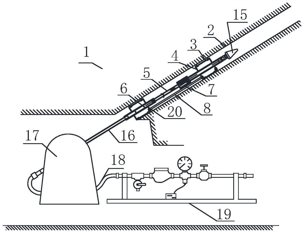
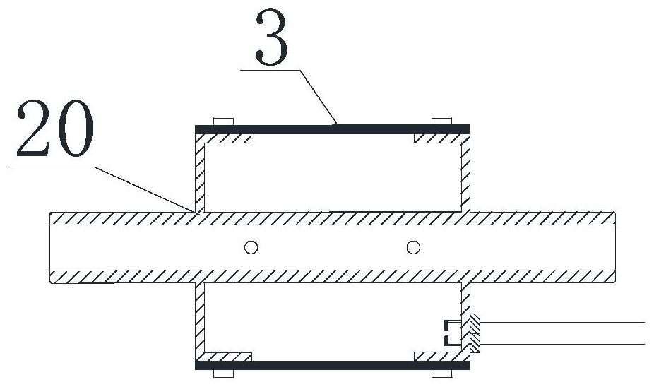
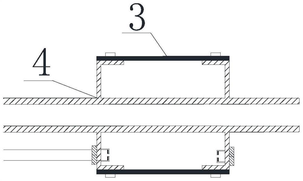
[0047] The present invention is an integrated detection device for mining damage range of rock mass in mines, which combines Figure 1 to Figure 4 As shown, it includes a plugging system, a guiding system, a leak detection system and a propulsion supply system. For details of the plugging system, see Figure 2 to Figure 4As shown, the closure system includes a type I closure support tube 20, a type II closure support tube 4, a closure capsule 3 and a capsule connecting tube 8; wherein the closure capsule includes a first closure capsule and a second closure capsule There is one type I plugging support tube 20 for the capsule, which is located a...


PUM


Abstract

The invention discloses an integrated detection device and a detection method for the mining damage range of mine rock mass, and relates to the technical field of determination of the damage range of mine floor rock mass. It includes a plugging system, a guiding system, a leak detection system and a propulsion supply system. The leak detection system includes a connecting pipe and a transfer switch. As one of the main improvement points, the transfer switch includes a cylindrical chamber, and the cylindrical chamber is set There are substrates, sliding valves and springs. The substrate is provided with water guide hole 2 and water guide hole 3. The sliding valve is provided with water guide hole 1. The sliding valve can slide freely inside the cylindrical chamber, and the water guide hole 1 can be respectively Two independent water guiding channels are formed with the second water guiding hole and the third water guiding hole. The invention uses a single external operating system to supply water, reduces the number of external systems, reduces the number of pipes in the borehole to one, and solves the problem of multi-pipeline winding in the borehole caused by too many external systems. The invention can improve the measurement efficiency and the accuracy of the measurement results.

Description

technical field [0001] The invention relates to the technical field of measuring the damage range of mine floor rock mass, in particular to an integrated detection device and a detection method for the mining damage range of mine rock mass. Background technique [0002] The measurement of the damage range of rock mass on the roof and floor of mine is an important parameter to indicate the occurrence state of coal rock. It is a key basic parameter in the study of mine water prevention and control. Therefore, to study the formation of water-conducting channels in mining surrounding rocks, it is necessary to grasp the movement rules of rock strata and determine the damage range of roof and floor rock mass. Numerical simulation, empirical formula prediction, field measurement and other methods are usually used. However, due to the complex site conditions, to a certain extent, the numerical simulation cannot reflect the site conditions well, and the blindness of the empirical fo...

Claims


Application Information

Patent Timeline
Patent Type & Authority Patents(China)
IPC IPC(8): E21B47/00E21B47/10E21B49/00E21B33/12
CPCE21B33/12E21B47/00E21B47/10E21B49/008
Inventor 赵志刚赵春波宋文成
Owner SHANDONG UNIV OF SCI & TECH
Why Eureka
Try Eureka