Antenna assembly and terminal

An antenna assembly and antenna technology, which is applied to antenna parts, antennas, antenna supports/installation devices, etc., can solve the problems of increasing the internal space occupancy rate of mobile phones, failing to achieve lightness and thinning of mobile phones, and complicated manufacturing processes, etc. Achieve the effect of ensuring reliability and stability of use, improving aesthetics, and reducing production costs

Pending Publication Date: 2018-03-23
MEIZU TECH CO LTD
View PDF6 Cites 1 Cited by
  • Summary
  • Abstract
  • Description
  • Claims
  • Application Information

AI Technical Summary

Problems solved by technology

In the related technology, the antenna of the mobile phone is in hard contact with the battery cover of the mobile phone through the shrapnel. Since the stroke of the shrapnel is relatively large, this structural setting increases the occupancy rate of the internal space of the mobile phone, which is not convenient for the layout of other parts of the mobile phone, and cannot To realize the lightness and thinning of the mobile phone, at the same time, the structure of the shrapnel is more complicated, and the production process is cumbersome. In addition, there is also a process method of radium engraving to engrave a single copper foil gasket and the metal shell of the mobile phone together to realize the antenna. The products processed by this process method have the disadvantages of low production efficiency and high processing cost.

Method used


Image

  • Antenna assembly and terminal
  • Antenna assembly and terminal
  • Antenna assembly and terminal

Examples


Embodiment Construction

[0040] In order to understand the above-mentioned purpose, features and advantages of the present invention more clearly, the present invention will be further described in detail below in conjunction with the accompanying drawings and specific embodiments. It should be noted that, in the case of no conflict, the embodiments of the present application and the features in the embodiments can be combined with each other.

[0041]In the following description, many specific details are set forth in order to fully understand the present invention. However, the present invention can also be implemented in other ways different from those described here. Therefore, the protection scope of the present invention is not limited by the specific details disclosed below. EXAMPLE LIMITATIONS.

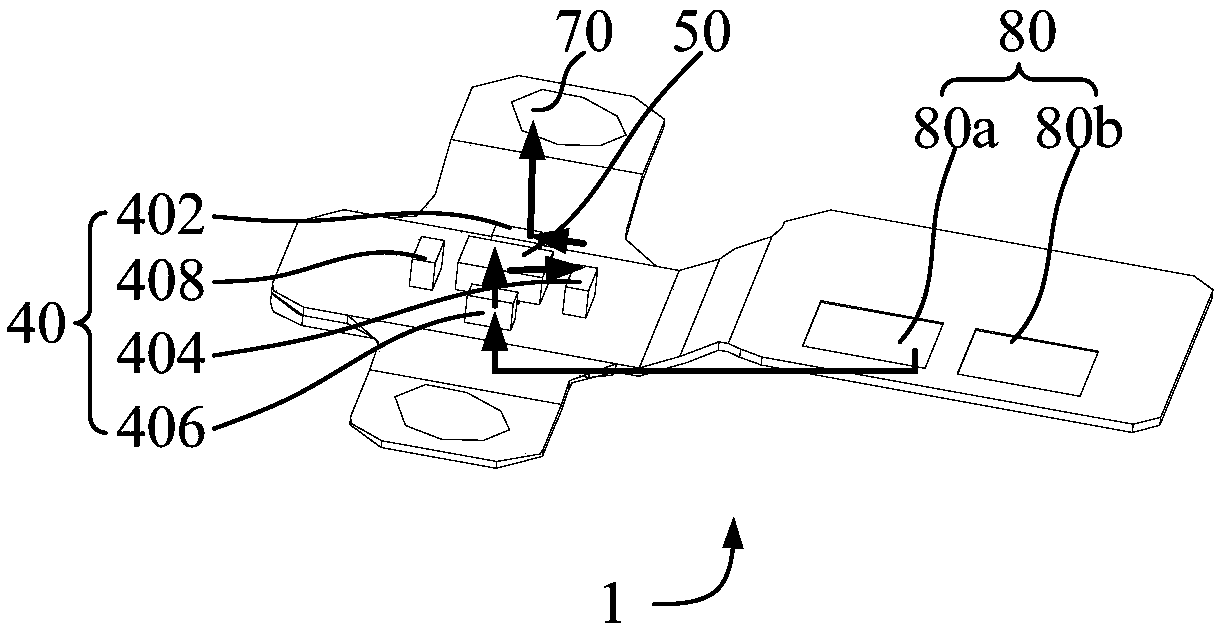
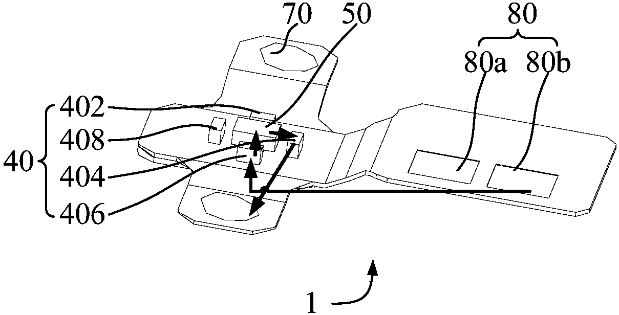
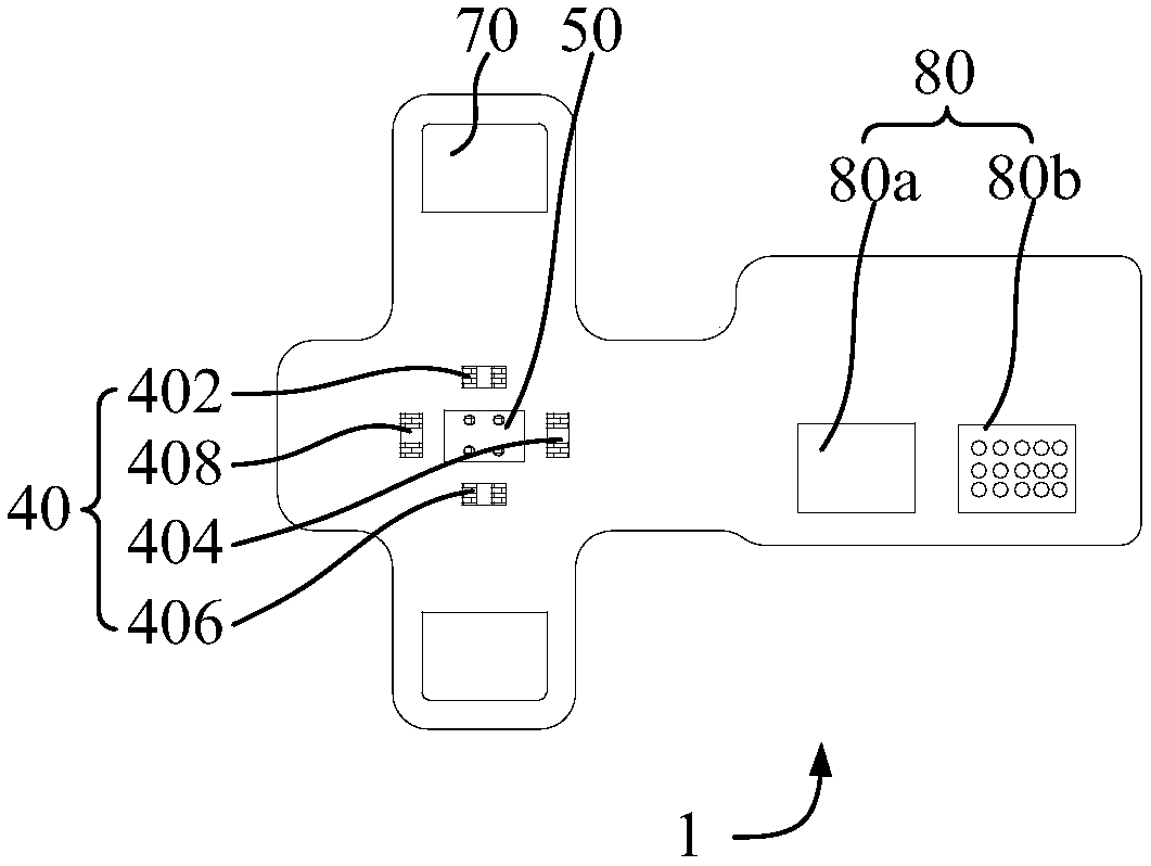
[0042] Refer below Figure 1 to Figure 6 The antenna assembly 1 and the terminal according to some embodiments of the present invention are described.

[0043] Such as Figure 1 to Figure 6 As show...


PUM


Abstract

The invention provides an antenna assembly which is used for a terminal, and the terminal is provided with a battery cover and a mainboard. The antenna assembly comprises a first antenna body, of which one end is connected with the battery cover; a second antenna body, which is opposite to the first antenna body; a connecting assembly, of which the two opposite ends are connected with the first antenna body and the second antenna body respectively; at least one connecting hole penetrating through the first antenna body, the connecting assembly and the second antenna body; and a conduction layer which is arranged on the hole wall of the at least one connecting hole; wherein the first antenna body and the second antenna body are conducted through the conduction layer. According to the structure of the antenna assembly, the size of the antenna assembly is reduced., so that the impedance value is reduced, the use reliability of the product is ensured. One end of the first antenna body is directly connected with a battery cover, so that the occupation rate of the antenna assembly in the internal space of the terminal is reduced, and the lightening and thinning of the product are realized.

Description

technical field [0001] The invention relates to the technical field of mobile phone processing, in particular to an antenna assembly and a terminal. Background technique [0002] As a kind of electronic communication device, mobile phone has been widely used in people's daily life. In the related technology, the antenna of the mobile phone is in hard contact with the battery cover of the mobile phone through the shrapnel. Since the stroke of the shrapnel is relatively large, this structural setting increases the occupancy rate of the internal space of the mobile phone, which is not convenient for the layout of other parts of the mobile phone, and cannot To realize the lightness and thinning of the mobile phone, at the same time, the structure of the shrapnel is more complicated, and the production process is cumbersome. In addition, there is also a process method of radium engraving to engrave a single copper foil gasket and the metal shell of the mobile phone together to re...

Claims


Application Information

Patent Timeline
Patent Type & Authority Applications(China)
IPC IPC(8): H01Q23/00H01Q1/24H01Q1/50H01Q1/36
CPCH01Q1/242H01Q1/36H01Q1/50H01Q23/00
Inventor 王元贞
Owner MEIZU TECH CO LTD
Why Eureka
Try Eureka