
Fertilizing device with function of crushing caking fertilizer

A fertilization device and fertilizer technology, applied in fertilization devices, fertilizer distributors, grain processing, etc., can solve problems such as low work efficiency, unfavorable mechanical fertilization, difficulties in storage, transportation and use, and achieve the effect of improving work efficiency

Inactive Publication Date: 2018-03-27
覃洁梅
View PDF0 Cites 3 Cited by
  • Summary
  • Abstract
  • Description
  • Claims
  • Application Information

AI Technical Summary

Problems solved by technology

[0002] China is a large agricultural country. With the development of modern agricultural science and technology, scientific and reasonable fertilization is the basic guarantee for maintaining sufficient and balanced water and soil nutrients, crop growth and stable yield, especially for large-scale farmland; In the process of production, processing, storage and transportation, agglomeration problems often occur, which brings many difficulties to storage, transportation and use. Serious agglomeration of chemical fertilizers is difficult to break, and partial agglomeration of chemical fertilizers is not good for mechanical fertilization, and it is easy to block the nozzle These will bring inconvenience to fertilization, and the fertilizer can only be fully absorbed by plants after the fertilizer is broken. The current fertilization device has the disadvantages of poor crushing effect, complicated operation, and low work efficiency.

Method used


Image

  • Fertilizing device with function of crushing caking fertilizer
  • Fertilizing device with function of crushing caking fertilizer
  • Fertilizing device with function of crushing caking fertilizer

Examples


Embodiment Construction

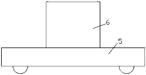
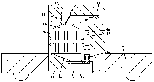
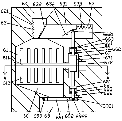
[0022] like Figure 1-Figure 6As shown, a fertilization device for broken and agglomerated fertilizers of the present invention includes a mobile car body 5 and a fertilization body 6, the mobile car body 5 is provided with a mounting groove 51, and the inner bottom wall of the mounting groove 51 is provided with a penetrating The discharge port 51 on the bottom end surface of the mobile vehicle body 5, the bottom of the fertilization body 6 is installed in the installation groove 51, and the bottom end surface of the fertilization body 6 is connected with the discharge port 51 and provided with a feeding trough 69. The fertilization machine body 6 is provided with a storage chamber 61, the top of the storage chamber 61 is connected with a feed chamber 65, the top of the feed chamber 65 is connected with a feed port 62, and the feed chamber 65 is connected with a feed port 62. The top of the feeding port 62 is connected with a feeding port 64 whose top runs through the top end...


PUM


Abstract

The invention discloses a fertilizing device with a function of crushing caking fertilizer. The fertilizing device comprises a moving vehicle body and a fertilizing machine. A mounting groove is arranged in the moving vehicle body. A material outlet passing through the end surface of the bottom of the moving vehicle body is arranged in the bottom wall of the mounting groove. The bottom of the fertilizing device is installed in the mounting groove. A feeding tank communicated with a discharge outlet is arranged in the end surface of the bottom of the fertilizing device. A material storage chamber is arranged in the fertilizing device. The top of the material storage chamber is communicated with a feeding chamber. A feeding inlet is communicated with the top of the feeding chamber. A material inlet of which the top passes through the end surface of the top of the fertilizing device is communicated with the top of the feeding inlet. A material discharge chamber of which the right bottom is communicated with the left top of the feeding tank is communicated with the bottom of the material storage chamber. A first cavity is arranged in the wall of the fertilizing device in the right sideof the material storage chamber. A second cavity is arranged in the wall of the fertilizing device above the first cavity. The fertilizing device has a simple structure, is easy to operate, improvescaking fertilizer breaking uniformity, reduces workers and labor and improves the precision of fertilization.

Description

technical field [0001] The invention relates to the technical field of agricultural machinery, in particular to a fertilization device for crushing agglomerated fertilizers. Background technique [0002] China is a big agricultural country. With the development of modern agricultural science and technology, scientific and rational fertilization is the basic guarantee for maintaining sufficient and balanced water and soil nutrients, as well as stable crop growth and yield, especially for large-scale farmland; In the process of production, processing, storage and transportation, the problem of agglomeration often occurs, which brings many difficulties to storage, transportation and use. The fertilizer is seriously agglomerated and difficult to break. However, these will bring inconvenience to fertilization, and plants can fully absorb the fertilizer fertility only after the fertilizer is broken. The current fertilization device has the shortcomings of poor crushing effect, com...

Claims


Application Information

Patent Timeline
Patent Type & Authority Applications(China)
IPC IPC(8): A01C15/12A01C15/00B02C18/14B02C1/04
CPCA01C15/12A01C15/007B02C1/04B02C18/14
Inventor 覃洁梅余达辉
Owner 覃洁梅
Learn More