Hardware stamping die

A stamping die and hardware technology, used in forming tools, manufacturing tools, metal processing equipment, etc., can solve the problems of poor heat dissipation of guide posts, generation of a lot of debris, poor shock absorption of molds, etc., to reduce debris and improve heat dissipation. , Good shock absorption effect

Inactive Publication Date: 2018-03-27
梅州华盛辉科技有限公司
View PDF4 Cites 19 Cited by
  • Summary
  • Abstract
  • Description
  • Claims
  • Application Information

AI Technical Summary

Problems solved by technology

[0003] However, the metal stamping dies currently on the market are not easy to take out when taking out the stamping parts, and it is easy

Method used


Image

  • Hardware stamping die
  • Hardware stamping die
  • Hardware stamping die

Examples


Embodiment

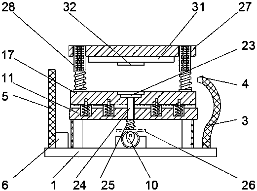
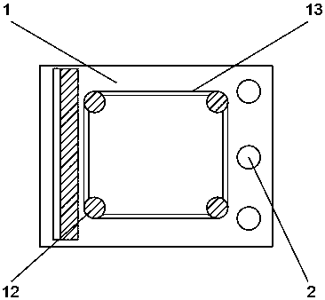
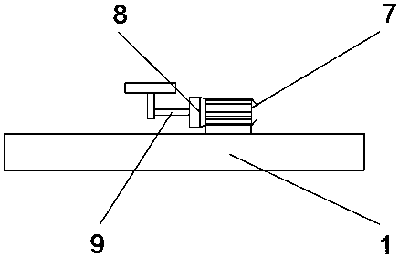
[0022] Example: such as Figure 1-5 As shown, the present invention provides a technical solution, a metal stamping die, including a base 1, a through hole 2, a metal hose 3, a nozzle 4, a chip baffle 5, an electromagnet 6, a motor 7, a reducer 8, a transmission Shaft 9, cam 10, damping plate 11, support rod 12, baffle plate 13, groove 14, positioning column 15, damping spring 16, lower template 17, positioning hole 18, buffer pad 19, push rod hole 20, stamping Groove 21, push plate groove 22, push plate 23, push rod 24, spring 25, push plate 26, upper template 27, guide post 28, sleeve 29, cooling groove 30, backing plate 31 and punch 32, base 1. A through hole 2 is evenly opened on one side of the top surface. A metal hose 3 is arranged inside the through hole 2. A nozzle 4 is installed on one end of the metal hose 3. A chip baffle 5 is installed on the other side of the top surface of the base 1. The chip baffle 5. An electromagnet 6 is installed on the side of the lower p...


PUM


Abstract

The invention discloses a hardware stamping die. The hardware stamping die comprises a base, a metal hose, a spray nozzle, a scrap blocking plate, an electromagnet, a cam, a vibration damper plate, damping springs, a buffer cushion, a material push plate, a sleeve and heat dissipation slots. One end of the metal hose is provided with the spray nozzle, the side face of the lower portion of the scrap blocking plate is provided with the electromagnet, and one end of an electromotor is provided with a speed reducer. One end of a transmission shaft is connected with the cam in a sleeved manner, thedamping plate is arranged above the base, the damping plate is connected with the base through supporting rods, and positioning pillars are sleeved with the vibration damper springs. The bottom faceof the material push plate is connected with a push rod, the bottom end of the push rod is connected with a push plate, and the outer side of the sleeve is uniformly provided with the heat dissipationslots. The electromotor is utilized to drive the cam to push the material push plate, materials are taken conveniently, and a workpiece is not prone to be damaged; the vibration damper springs in thedamping plate are utilized to absorb vibration generated in the stamping process, vibration reduction performance is good, and the die is not prone to be damaged; and scraps are blown away through the metal hose connected with an air pump and blocked by the scrap blocking plate, and stamping and cleaning are facilitated.

Description

technical field [0001] The invention relates to the technical field of metal processing, in particular to a metal stamping die. Background technique [0002] Metal stamping is a process that uses a punch to deform or break stainless steel, iron, aluminum, copper and other plates and heterogeneous materials to achieve a certain shape and size. To make the plate reach the required shape, the stamping die is necessary. [0003] However, the metal stamping dies currently on the market are not easy to take out when taking out the stamping parts, and it is easy to cause damage to the workpiece if it is taken out forcibly. It is not easy to clean, and the heat dissipation of the guide post is poor. Contents of the invention [0004] The present invention provides a metal stamping die, which can effectively solve the problems raised in the above-mentioned background technology. [0005] In order to achieve the above object, the present invention provides the following technical...

Claims


Application Information

Patent Timeline
IPC IPC(8): B21D37/10B21D37/16B21D45/04B08B5/02B03C1/02F16F15/04
CPCB21D37/10B03C1/02B08B5/02B21D37/16B21D45/04F16F15/04
Inventor 魏庆锌
Owner 梅州华盛辉科技有限公司
Why Eureka
Try Eureka