Puncher for steel plate

A puncher, steel plate technology, applied in boring/drilling, drilling/drilling equipment, clamping, etc., can solve the problems of influence, waste of lubricating oil, low efficiency, etc., to reduce errors and waste , the effect of reducing costs

Inactive Publication Date: 2018-03-27
胡振锋
View PDF10 Cites 25 Cited by
  • Summary
  • Abstract
  • Description
  • Claims
  • Application Information

AI Technical Summary

Problems solved by technology

[0003] During the production process of the steel plate, drilling operations are often required, but the existing steel plate is drilled through a drilling machine or a drilling rig, and the position of the drilling machine or drilling machine needs to be adjusted, and the position of the steel plate cannot be fixed, resulting in large errors and high costs. The efficiency is low. At the same time, in

Method used


Image

  • Puncher for steel plate
  • Puncher for steel plate

Examples


Embodiment Construction

[0018] The following will clearly and completely describe the technical solutions in the embodiments of the present invention with reference to the accompanying drawings in the embodiments of the present invention. Obviously, the described embodiments are only some, not all, embodiments of the present invention. Based on the embodiments of the present invention, all other embodiments obtained by persons of ordinary skill in the art without making creative efforts belong to the protection scope of the present invention.

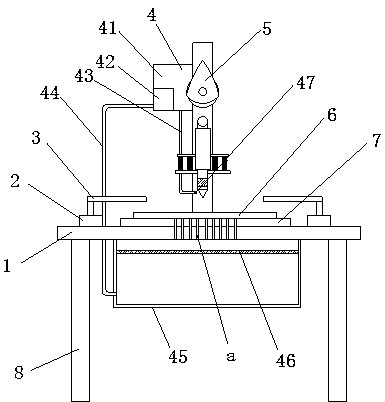
[0019] see Figure 1-2 , the present invention provides a technical solution: a steel plate puncher, including a device main body, a lubricating oil spraying mechanism 4 and a punching mechanism 5, the device main body includes a base 1, a cylinder 2, a positioning plate 3, a straight column 6, and a steel plate body 7. The workbench 8 and the supporting feet 9, the supporting feet 9 are set on the lower end surface of the base 1, and there are two cylinders 2...


PUM


Abstract

The invention relates to a puncher for a steel plate. The puncher comprises cylinders, locating plates, a workbench, a cam, a connecting ball, a connecting rod, a telescopic pipe, a drill, a driving motor, an oil tank, an oil pump, an oil supply pipe, an oil return pipe, an oil collecting tank, a filter screen and an oil nozzle, wherein output shafts of the cylinders are fixedly connected with thelocating plates; the workbench is arranged in the middle position of the upper end face of a base; the cam is fixedly connected with the output end of the driving motor; the connecting ball is fixedly arranged on the upper end face of the connecting rod; and the lower end of the connecting rod is connected with the drill through the telescopic pipe. According to the puncher, the steel plate is punched through electric energy, the position of the drill does not need to adjusted, errors are decreased, cost is reduced, efficiency is improved, the oil nozzle is connected with the oil tank throughthe oil supply pipe, the filter screen is arranged on the upper side in the oil collecting tank, the oil pump is connected with the bottom end in the oil collecting tank through the oil return pipe,lubricating oil can be automatically sprayed onto the drill, labor force is reduced, redundant lubricating oil can be recycled, and waste of lubricating oil is reduced.

Description

technical field [0001] The invention relates to the field of mechanical equipment, in particular to a steel plate puncher. Background technique [0002] The steel plate is a flat steel material that is poured with molten steel and pressed after cooling. Steel plates are flat, rectangular and can be rolled directly or cut from wide strips. Steel plates are classified according to thickness, thin steel plates < 4 mm (thinnest 0.2 mm), medium-thick steel plates 4-60 mm, and extra-thick steel plates 60-115 mm. Steel plates are divided into hot rolling and cold rolling according to rolling. The width of the thin plate is 500~1500 mm; the width of the thick plate is 600~3000 mm. Sheets are classified by steel type, including ordinary steel, high-quality steel, alloy steel, spring steel, stainless steel, tool steel, heat-resistant steel, bearing steel, silicon steel, and industrial pure iron sheets, etc.; by professional use, there are plates for oil drums, Enamel plates, bu...

Claims


Application Information

Patent Timeline
IPC IPC(8): B23Q3/08B23Q11/10B23B39/00
CPCB23Q3/08B23B39/00B23Q11/10B23Q2703/04
Inventor 胡振锋
Owner 胡振锋
Why Eureka
Try Eureka