
Ring-cable joint for irregular plane cable net

An irregular, ring-cable technology, applied in the dome roof structure, building components, arched structure, etc., can solve the problems of increasing the difficulty of processing and manufacturing ring-cable joints, increasing the cost of joint processing and manufacturing, and unfavorable standardized production of joints. Simple structure, convenient operation, saving design effect

Pending Publication Date: 2018-03-27
WEIFANG UNIVERSITY
View PDF0 Cites 1 Cited by
  • Summary
  • Abstract
  • Description
  • Claims
  • Application Information

AI Technical Summary

Problems solved by technology

At present, the commonly used ring cable nodes often make fixed connections between the connecting ear plate of the radial cable or the oblique cable and the ring cable connector. In the regular plane cable network, one or a limited number of ring cable nodes can be used to achieve the cable network connection. In the irregular planar cable network structure, the traditional node form will significantly increase the types of ring cable nodes, which not only increases the difficulty of manufacturing ring cable nodes, but also is not conducive to the standardized production of nodes, thereby increasing the cost of node processing and manufacturing.

Method used


Image

  • Ring-cable joint for irregular plane cable net
  • Ring-cable joint for irregular plane cable net
  • Ring-cable joint for irregular plane cable net

Examples


Embodiment 1

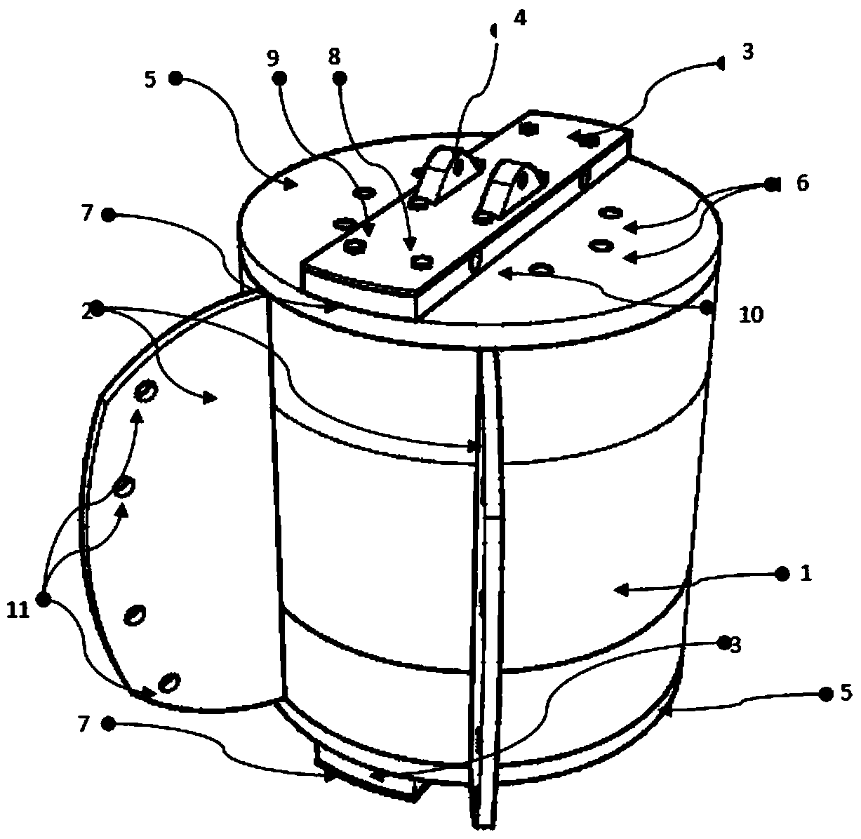
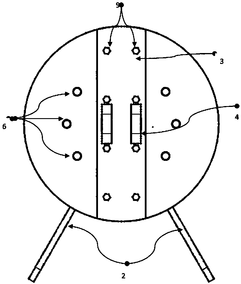
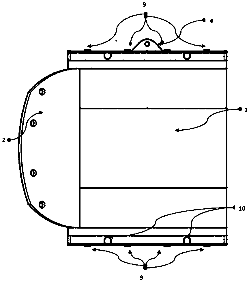
[0019] The main structure of this embodiment includes: pin shaft connecting body 1, oblique cable ear plate 2, hoop cable connecting body 3, pin shaft end plate 5, countersunk bolt 6, high-strength bolt 9, hoop cable hole 10, and oblique cable connecting hole 11 ; The pin connecting body 1 is located at the center of the node, and it is respectively welded or bolted to the oblique cable lug plate 2 and the ring cable connecting body 3; the top and bottom of the pin connecting body 1 are symmetrically provided with a pin end plate 5, and the pin shaft The end plate 5 is fixed to the pin shaft connecting body 1 through the countersunk bolt 6, and is connected to the hoop connecting body 3 through the high-strength bolt 9. The hoop connecting body 3 is composed of the hoop connecting plate 7 and the cover plate 8, and the hoop connecting plate 7 There is a cable hole 10 on the top, and the cover plate 8 is connected with the hoop connecting plate 7 through high-strength bolts 9, w...

Embodiment 2

[0021] The main structure of this embodiment includes: pin shaft connecting body 1, oblique cable ear plate 2, ring cable connecting body 3, vertical bar connecting ear plate 4, pin shaft end plate 5, countersunk bolt 6, high-strength bolt 9, ring cable hole 10. Cable connection hole 11; the pin connector 1 is located at the center of the node, which is welded or bolted to the oblique cable ear plate 2, the ring cable connector 3 and the vertical rod connecting ear plate 4 respectively; the pin connector 1 The top and the bottom are symmetrically provided with pin shaft end plates 5, which are fixed to the pin shaft connecting body 1 by countersunk bolts 6, and connected to the ring cable connecting body 3 by high-strength bolts 9, and the ring cable connecting body 3 is connected by the ring cable The connecting plate 7 and the cover plate 8 are composed, the cable hole 10 is opened on the cable connecting plate 7, the cover plate 8 is connected with the cable connecting plate...

Embodiment 3

[0023] The main structure of this embodiment includes: pin shaft connecting body 1, oblique cable ear plate 2, ring cable connecting body 3, vertical bar connecting ear plate 4, pin shaft end plate 5, countersunk bolt 6, high-strength bolt 9, ring cable hole 10. Cable connection hole 11; the pin connector 1 is located at the center of the node, which is welded or bolted to the oblique cable ear plate 2, the ring cable connector 3 and the vertical rod connecting ear plate 4 respectively; the pin connector 1 The top and the bottom are symmetrically provided with pin shaft end plates 5, which are fixed to the pin shaft connecting body 1 by countersunk bolts 6, and connected to the ring cable connecting body 3 by high-strength bolts 9, and the ring cable connecting body 3 is connected by the ring cable The connecting plate 7 and the cover plate 8 are composed, the cable hole 10 is opened on the cable connecting plate 7, the cover plate 8 is connected with the cable connecting plate...


PUM


Abstract

The invention belongs to the technical field of building structures, and relates to a ring-cable joint for an irregular plane cable net. A pin shaft rotating ring is mounted on a pin shaft to form a pin shaft connecting body in a sleeving mode, and the pin shaft connecting body is connected with an oblique cable lug plate, a ring-cable connecting body and a vertical rod connecting lug plate; an upper pin shaft end plate and a lower pin shaft end plate are correspondingly arranged at the top and the bottom of the pin shaft connecting body, the oblique cable lug plate is fixedly mounted on the outer side surface of the pin shaft connecting body, the upper pin shaft end plate and the lower pin shaft end plate are connected with the ring-cable connecting body through high-strength bolts, and the ring-cable connecting body is formed by connecting a ring-cable connecting plate with a cover plate through the high-strength bolts; a cable hole is formed in the ring-cable connecting plate, an external connecting ring cable penetrates through the cable hole to be connected with the ring-cable connecting body; and the vertical rod connecting lug plate is welded to the cover plate, and an externally-connected vertical supporting rod is connected with the joint through the vertical rod connecting lug plate. According to the ring-cable joint for the irregular plane cable net, the structure issimple, the principle is scientific, operation is convenient, an included angle between a radial cable and the ring cable can be changed at will, standardized manufacturing can be realized, and the manufacturing cost is low.

Description

Technical field: [0001] The invention belongs to the technical field of building structures, and relates to a hoop cable node of a prestressed steel structure of a cable rod, in particular to a hoop cable node for an irregular plane cable net. Background technique: [0002] The cable-strut prestressed structure is a kind of spatial structural system that is composed of cables and rods as the basic units, and the structural rigidity is provided by prestressing. The cable-strut prestressed structure can be traced back to the tensioned overall structure proposed by the famous American architect R.B.Fuller in the 1940s. Following Fuller, many scholars and engineers have analyzed and interpreted this type of structural system from different angles. In the 1980s, B.H.Geiger and M.Levy in the United States further evolved and developed Fuller's ideas, and proposed a cable dome structure and applied it to practical engineering. After the emergence of flexible prestressed structure...

Claims


Application Information

Patent Timeline
IPC IPC(8): E04B1/32E04B1/58
CPCE04B1/32E04B1/58
Inventor 邢栋柳长江刘海宁寇海磊
Owner WEIFANG UNIVERSITY
Features
  • Generate Ideas
  • Intellectual Property
  • Life Sciences
  • Materials
  • Tech Scout
  • Unparalleled Data Quality
  • Higher Quality Content
  • 60% Fewer Hallucinations
Learn More