
Speed-increasing drilling bit for downhole local pressure reducing

A kind of drill bit and partial technology, applied in the direction of drill bit, drilling equipment, earthwork drilling and production, etc., can solve the problems of mud column pressure drop, unusable, blowout accidents, etc., to improve drilling speed, improve cutting efficiency, and ensure pressure reduction effect Effect

Pending Publication Date: 2018-03-27
邓立宇
View PDF10 Cites 1 Cited by
  • Summary
  • Abstract
  • Description
  • Claims
  • Application Information

AI Technical Summary

Problems solved by technology

At present, the method of reducing the pressure of the mud column at the bottom of the well is to reduce the mud density in the well, but reducing the mud density will lead to a decrease in the mud column pressure of the entire wellbore, and cannot provide sufficient support and pressure for the well wall of the drilled well section, which may easily lead to Collapse and blowout accidents, unusable for many formations

Method used


Image

  • Speed-increasing drilling bit for downhole local pressure reducing
  • Speed-increasing drilling bit for downhole local pressure reducing
  • Speed-increasing drilling bit for downhole local pressure reducing

Examples


Embodiment 1

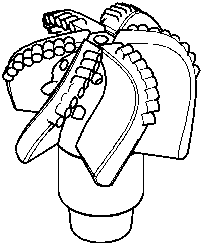
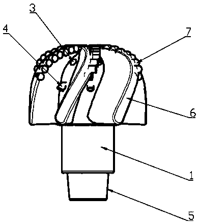
[0022] A speed-increasing drill bit for local decompression at the bottom of a well, such as Figure 1-7 As shown, including an alloy steel core 1, a plurality of blades 6 are evenly distributed on the alloy steel core 1, and the blades 6 are in the shape of turbine blades and the tops are gathered on the center line of the alloy steel core 1; the blades 6 are provided with diamond The cutting teeth 7; the number of blades 6 are six; the blades 6 and the alloy steel core 1 are of an integrated structure.

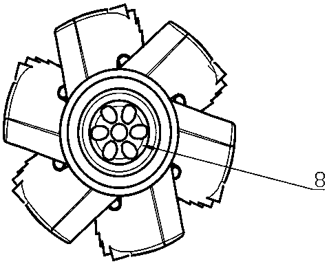
[0023] The alloy steel core 1 is provided with a central water hole 8; the top confluence of the blades 6 is provided with a central nozzle 2 communicating with the central water hole 8, and an upper side nozzle 3 is provided between adjacent blades 6. Reverse nozzles 4 are also provided between adjacent blades 6 . The upper side nozzle 3 is located between the reverse nozzle 6 and the central nozzle 2 ; the upper side nozzle 3 and the reverse nozzle 6 are both in communica...

Embodiment 2

[0025] A speed-increasing drill bit for partial decompression at the bottom of a well, comprising an alloy steel core, on which a plurality of blades are uniformly distributed, the blades are in the shape of turbine blades and their tops are gathered on the center line of the alloy steel core; There are diamond cutting teeth; the number of blades is 9; the blades and the alloy steel core are an integrated structure.

[0026] A central water hole is provided inside the alloy steel core; a central nozzle connected to the central water hole is provided at the top confluence of the blades, and upper side nozzles are also provided between adjacent blades. Reverse nozzles are also provided between adjacent blades. The upper side nozzle is located between the reverse nozzle and the central nozzle; the upper side nozzle and the reverse nozzle are both in communication with the central water hole. The blades are set obliquely and the angle of inclination is 75°. The reverse nozzle is...

Embodiment 3

[0028] The reverse nozzle is arranged on the blade.


PUM


Abstract

The invention belongs to the technical field of drilling tool equipment, and specifically discloses a speed-increasing drilling bit for downhole local pressure reducing. The speed-increasing drillingbit comprises an alloy steel core, and a plurality of cutter blades are evenly distributed on the alloy steel core; the cutter blades are each in a turbine blade shape, and the top ends of the cutterblades are converged in the center line of the alloy steel core; the cutter blades are provided with diamond cutting teeth; and the number of the cutter blades is 5-9, and the cutter blades and the alloy steel core are of an integrated structure. The speed-increasing drilling bit for downhole local pressure reducing can effectively improve the drilling speed and has good stability.

Description

technical field [0001] The invention belongs to the technical field of drilling equipment, and relates to a drill bit, in particular to a speed-increasing drill bit with local decompression at the bottom of a well. Background technique [0002] The rock-breaking effect of diamond drill bits is not only related to lithology and external factors, but also the fluid column pressure in the well is an extremely important factor affecting the ROP. The "isotropic compression effect" leads to an increase in the indentation strength and plasticity of the rock, a reduction in the volume of the crushing pit during the crushing process, and a decrease in the drilling speed. A large number of field results show that reducing the bottom hole mud column pressure can greatly increase the penetration rate, and the underbalanced drilling and gas drilling rate increase are proposed based on this principle. At present, the method of reducing the pressure of the mud column at the bottom of the ...

Claims


Application Information

Patent Timeline
Patent Type & Authority Applications(China)
IPC IPC(8): E21B10/43E21B10/54E21B10/60
CPCE21B10/43E21B10/54E21B10/602
Inventor 邓金根董星亮张春阳邓立宇侯斌
Owner 邓立宇
Learn More