Integrated drying oven
An integrated oven technology, applied in drying, drying machine, drying solid materials, etc., can solve the problem of high cost of production site use, achieve the effect of small footprint, simple structure, and good drying effect
- Summary
- Abstract
- Description
- Claims
- Application Information
AI Technical Summary
Problems solved by technology
Method used
Image

Examples
Embodiment Construction
[0015] Specific embodiments of the present invention will be described in detail below in conjunction with the accompanying drawings.
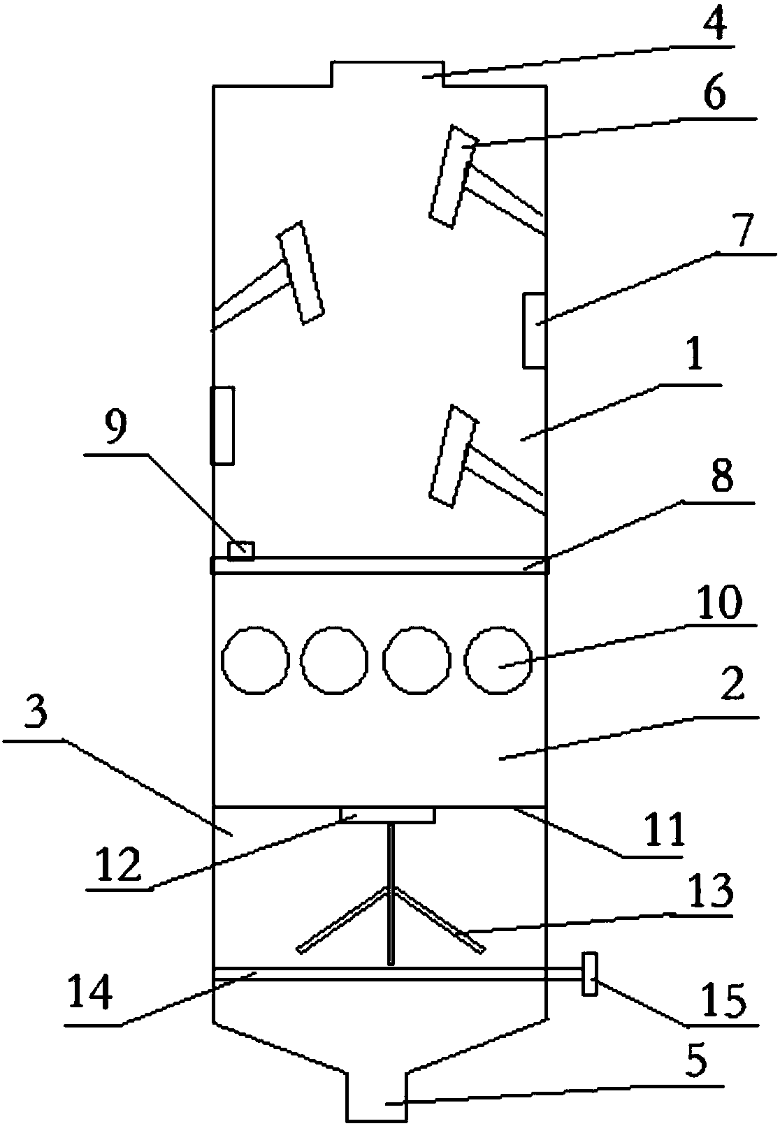
[0016] like figure 1 As shown, an integrated oven includes an oven body, and an insulation layer is provided outside the oven body. The oven body is divided into a transfer chamber 1, a drying chamber 2, and a mixing chamber 3 from top to bottom. The top of the oven body is provided with a feed inlet 4, and the bottom is provided with a tapered outlet 5, and a heating tube 7 and a baffle 6 are arranged on the side wall of the transfer chamber 1 in the oven body, and the baffle 6 are arranged in a staggered manner, the baffles 6 and the heating pipes 7 are arranged in a staggered manner, and under the baffles 6 there is a leaky net 8 for the rubber to pass through, and the mesh of the leaky net 8 is larger than the cross-sectional area of the rubber. A vibrator 9 is provided on the leaking screen 8 to accelerate rubber passing through the le...
PUM
 Abstract
Description
Claims
Application Information