Flowmeter verification device and verification method thereof

A verification device and flowmeter technology, which is applied to measurement devices, test/calibration devices, liquid/fluid solid measurement, etc., can solve the problems of inaccurate measurement density, slow temperature changes, and large measurement errors, and achieves the effect of errors. The effect of few factors, accurate verification data, and accurate volume measurement

Inactive Publication Date: 2018-03-27
李盛
View PDF10 Cites 11 Cited by
  • Summary
  • Abstract
  • Description
  • Claims
  • Application Information

AI Technical Summary

Problems solved by technology

[0003] In the verification of the existing flowmeter volumetric method, first measure the liquid volume V in the standard measuring tank, and then measure the temperature with a mercury thermometer or a digital display thermometer, because the temperature of the liquid is inconsistent with the temperature of the tank body and the ambient temperature, the temperature will change slowly during the measurement process , need constant temperature correction, and use standard metal utensils as volume standards, due to factors such as thermal expansion and contraction affected by the ambient temperature, the measurement error is large
[0004] In the mass method flowmeter verification, because a density meter is needed, and the density meter is affected by temperature changes, environmental changes and the accuracy level of the density meter during the actual measurement process, the measurement density is inaccurate and the error is large, and the density meter can only be single point. Sampling measurement, in the actual use process, the density measurement value is different every time, and the existing method has cumbersome measurement steps, introduces many sources of uncertain factors, and the volatility of the liquid affects the actual flowmeter measurement effect

Method used


Image

  • Flowmeter verification device and verification method thereof
  • Flowmeter verification device and verification method thereof
  • Flowmeter verification device and verification method thereof

Examples


Embodiment Construction

[0049] In order to illustrate the present invention in detail, the present invention will be further described in detail below in conjunction with specific implementation examples, but the described examples should not be interpreted in a limiting manner.

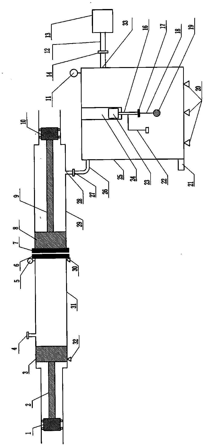
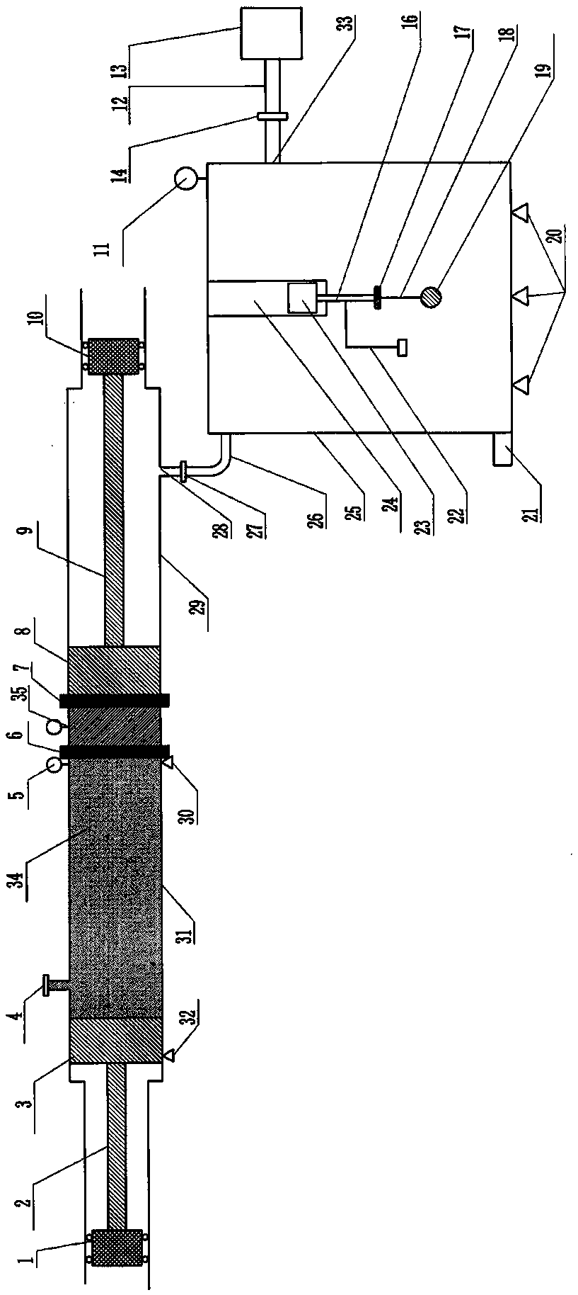
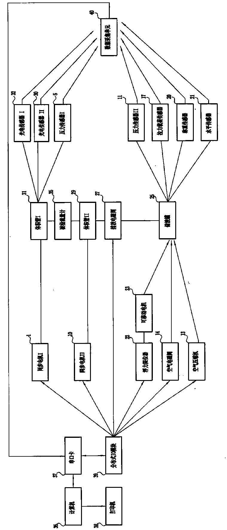
[0050] from figure 1 , image 3 It can be seen from the figure that the flowmeter verification device of the present invention includes volume tube I31, volume tube II29, working piston I3, working piston II8, synchronous motor I1, synchronous motor II10, pressure sensor I5, pressure sensor II11, photoelectric sensor I32, photoelectric Sensor II 30, discharge solenoid valve 27, level sensor 21, liquid storage tank 25, air solenoid valve 14, air compressor 13, buoyancy limiter 22, movable motor 23, tensile load sensor 17, weighing sensor 20, standard metal Sphere 19, data acquisition unit 40, distributed IO module 39, computer 36, serial port card 37, printer 38, wherein, the volume tube I31, volume tube II29 and the measur...


PUM


Abstract

Provided are a flowmeter verification device and a verification method thereof. The device comprises a volume pipe I31, a volume pipe II29, a working piston I and a working piston II which are arranged in the volume pipe I and the volume pipe II, a synchronous motor I and a synchronous motor II which are connected with the working piston I and the working piston II, a photoelectric sensor I and aphotoelectric sensor II which are installed on the volume pipe I, a liquid storage tank 25 connected with the volume pipe II, a data collection unit 40, a computer and the like, a flowmeter to be verified is installed at the two ends of the volume pipe I and the volume pipe II, liquid which is the same as liquid flowing through the flowmeter actually is injected into the volume pipe I, the synchronous motor I and the synchronous motor II drive the working piston I and the working piston II to work to trigger the photoelectric sensor I and the photoelectric sensor II, time for the liquid to flow through the flowmeter to be verified is read, then the liquid is discharged into the liquid storage tank so that the volume of the liquid which flows through the flowmeter to be verified can be measured, the normal flow which flows through the flowmeter to be verified is calculated, according to readout data of the flowmeter to be verified, a readout error is calculated, and according to the error, whether or not the flowmeter is qualified is judged. According to the device and the method, measurement is convenient, and the data is accurate.

Description

technical field [0001] The invention designs a flowmeter verification device and a verification method thereof. Background technique [0002] The commonly used methods for on-site verification of liquid volumetric flowmeters are the volumetric method (open structure of the container); the common methods for the verification of mass flowmeters are the volumetric method and the mass method. 1. The volumetric method is to use a standard measuring tank to measure the volume value of the liquid passing through the flowmeter and the time for the liquid to flow through the flowmeter to obtain the flow value; 2. The mass method needs to be used in conjunction with a density meter and measured using a standard density meter The density value of the medium flowing through the flowmeter and the time for the liquid to flow through the flowmeter, and then indirectly measure the volume of the medium flowing through the flowmeter according to the density formula, so as to obtain the flow v...

Claims


Application Information

Patent Timeline
Patent Type & Authority Applications(China)
IPC IPC(8): G01F25/00
CPCG01F25/00G01F25/11G01F25/14
Inventor 李盛
Owner 李盛
Why Eureka
Try Eureka