Printing method using two lasers

A laser printing and laser technology, applied in lasers, laser parts, removing conductive materials by mechanical methods, etc., can solve problems such as incompatibility, inability to eliminate metal stars, high particle pollution, etc.

Active Publication Date: 2018-03-27
CENT NAT DE LA RECHERCHE SCI +1
View PDF8 Cites 2 Cited by
  • Summary
  • Abstract
  • Description
  • Claims
  • Application Information

AI Technical Summary

Problems solved by technology

[0029] However, as noted in the aforementioned article, the process has some drawbacks, notably the magnitude of the energy required to eject a single droplet of metal large enough to similarly eject many nearly indestructible metallic stars
This approach thus results in high particle contamination, which is not compatible with most applications in the microelectronics field

Method used


Image

  • Printing method using two lasers
  • Printing method using two lasers
  • Printing method using two lasers

Examples


Embodiment Construction

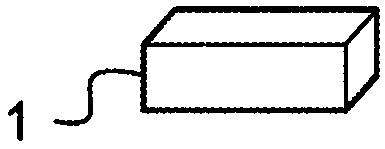
[0047] refer to figure 1 , the basic principles of the LIFT method known in the prior art will now be described.

[0048] therefore, Figure 1a A laser energy source 1 capable of generating laser energy 10 is shown.

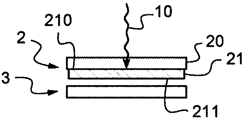
[0049] It also shows a target substrate 2 comprising a transparent substrate 20 and a coating 21 consisting of a thin liquid film.

[0050] Figure 1a A receiver substrate 3 is also shown.

[0051] The target substrate 2 is located between the laser energy source 1 and the receiver substrate 3 .

[0052] Furthermore, a coating 21 is formed on the surface of the substrate 20 facing the receiver substrate 3 . Coating 21 thus comprises a surface 210 in contact with substrate 20 and a surface 211 facing receiver substrate 3 .

[0053] The coating 21 can consist of an ink based on silver or copper nanoparticles.

[0054] Once the target substrate 2 and the receiver substrate 3 as Figure 1a The coating 21 is irradiated by the laser energy source 1 in the arran...


PUM

PropertyMeasurementUnit
thicknessaaaaaaaaaa
thicknessaaaaaaaaaa

Abstract

The invention relates to a laser printing method comprising the following steps: (a) providing a receiving substrate (4); (b) providing a target substrate (5) including a transparent substrate (50), one face of which has a coating (51) formed by a solid metal film; (c) locally irradiating the film (51) through the transparent substrate (50) using a first laser (8) in order to reach the melting point of the metal in a target zone of the film that is in liquid form; (d) irradiating the liquid film through the transparent substrate using a second laser on the target zone defined in step (c), in order to form a liquid jet in the target zone and to eject same from the substrate in the form of molten metal; (e) depositing a drop of molten metal on a defined receiving zone of the receiving substrate, the drop solidifying as it cools.

Description

technical field [0001] The present invention relates to the technical field of electronic printing, and more specifically, to a laser printing method. Background technique [0002] The realization of electronic circuits on flexible substrates is an important step in the development of connected devices and objects and their applications, especially in the fields of healthcare, logistics and distribution. The fabrication of these objects requires many different technological steps, especially the printing of conductive microscale or microstructures to deal with the problems associated with interconnections. [0003] There are two families of electronic printing technologies, which can be defined as: [0004] Ultra-high-speed technologies derived from traditional printing techniques, such as flexo printing or offset printing, require the preparation of engraved rolls or masks and are able to print only a single design at ultra-high speed. [0005] Digital technology is much ...

Claims


Application Information

Patent Timeline
Patent Type & Authority Applications(China)
IPC IPC(8): H05K3/02B41J2/475H05K3/04
CPCH05K3/025H05K3/046H05K3/10H05K2201/0257H05K2203/0528H05K2203/108H05K2201/0104B41J2/442B41M5/50H01S3/00H05K3/1275H05K2203/0736H05K2203/128
Inventor 安妮·帕特丽夏·布兰奇·阿隆尼勒菲力浦·克里斯汀·莫里斯·德拉波特
Owner CENT NAT DE LA RECHERCHE SCI
Why Eureka
Try Eureka