Combined veneer reeling machine

A technology of plate rolling machine and frame, which is applied in the field of sheet material processing, can solve the problems of inconvenient work, burns, etc., and achieve the effect of facilitating the work of retrieving materials, increasing the cooling speed, and increasing the contact area

Active Publication Date: 2018-03-30
JIANGSU MINGYU NEW ENERGY RESOURCES
View PDF5 Cites 2 Cited by
  • Summary
  • Abstract
  • Description
  • Claims
  • Application Information

AI Technical Summary

Problems solved by technology

[0003] During the coiling process, due to the bending and extrusion of the steel plate, a large amount of heat will be generated. After the coiling is completed, the staff needs to manually remove the processed plate from the coiling machine. High temperature, the staff is prone to burns when they are not paying attention, causing inconvenience to work

Method used


Image

  • Combined veneer reeling machine
  • Combined veneer reeling machine
  • Combined veneer reeling machine

Examples


Embodiment 1

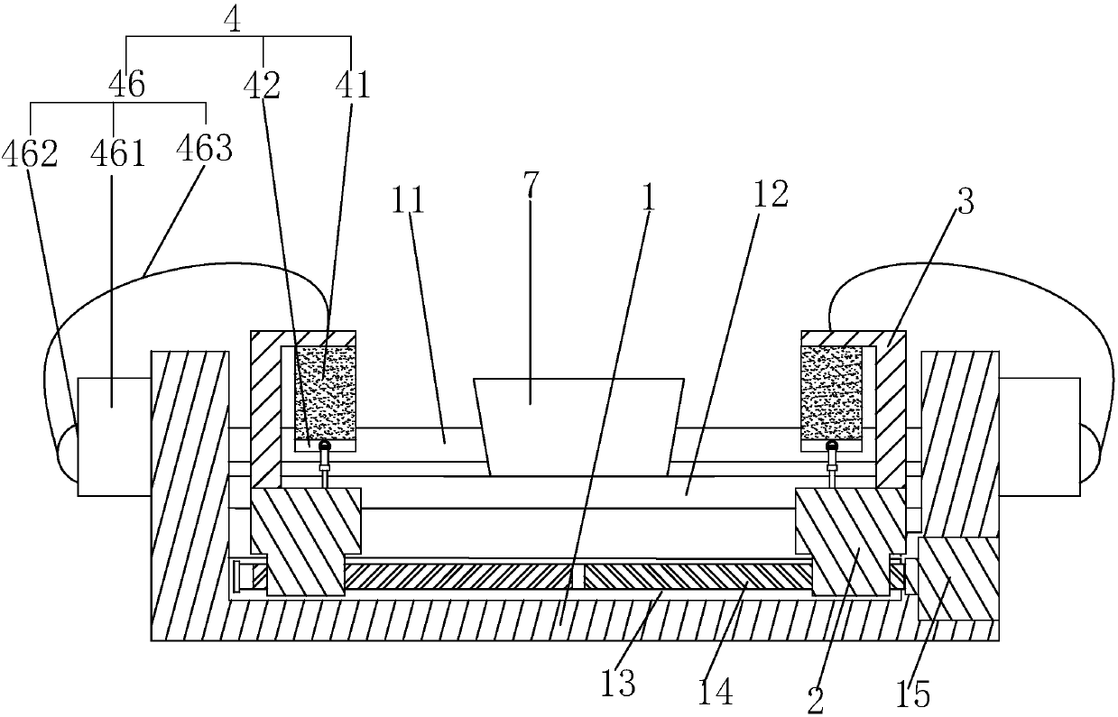
[0032] Embodiment 1: a kind of combination bending machine, such as figure 1 As shown, it includes the frame 1, the upper roller, the lower roller 12 and the transmission source (not shown in the figure), etc., the upper roller is the main transmission roller, connected with the power source, and the lower roller 12 moves vertically to clamp the plate. Through the rotation of the upper roller 11, the process of curling the plate can be realized.

[0033] Such as figure 1 As shown, at this time, a guide rail 13 parallel to the upper stick 11 is provided on the frame 1, a working screw 14 connected with the drive motor 15 is arranged in the guide rail 13, and the two ends of the working screw 14 are respectively provided with a left-hand thread and a right-hand thread. screw thread, that is, the working screw 14 is a double-helix screw, and the two ends of the working screw 14 are screwed with a slider 2, and the working screw 14 rotates under the work of the drive motor 15, so...

specific Embodiment approach

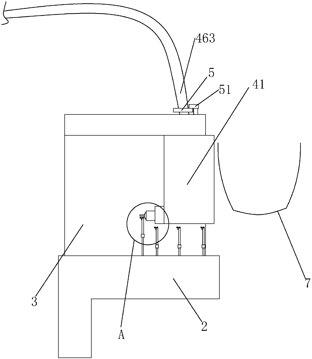
[0035]Specific implementation method: after the coiling plate 7 finishes the processing work, the drive motor 15 works, the working screw 14 rotates, and the two sliders 2 move towards each other to the position close to the coiling plate 7 at the same time, during this process, the water pump 462 works to control the water storage tank The water liquid in 461 enters in the outlet pipe 463, and flows into the sponge pad 41 to soak the sponge pad 41. When the slider 2 drives the sponge pad 41 close to the coil 7, the soaked sponge pad 41 can be connected to the coil 7. The outer surface is in contact, and the water liquid in the sponge pad 41 contacts the coiled plate 7 to realize the heat absorption work to the coiled plate 7; in this process, because the sponge pad 41 has good elasticity and deformation performance, it can The curling degree of this batch of coiled plates 7 is adjusted to the shape of the sponge pad 41, so that the shape of the sponge pad 41 fits the curved sh...

Embodiment 2

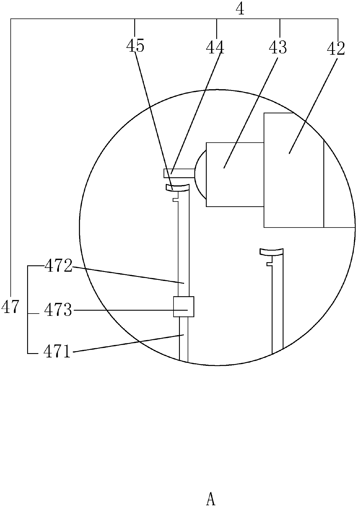
[0039] Embodiment 2: A combined plate bending machine, the difference from Embodiment 1 is that, as Figure 5 and 6 As shown, at this time, a connecting plate 31 arranged parallel to the slider 2 is hinged at the top of the support frame 3 near the sponge pad 41, and a piece of connecting plate 31 perpendicular to the connecting plate 31 is embedded in a sliding buckle on the lower surface of the connecting plate 31. Heat dissipation plate 32, heat dissipation plate 32 realizes the sliding connection on connection plate 31 by moving fast, and also is provided with sponge pad 41 on the side of heat dissipation plate 32 close to support frame 3, and also is provided with control heat radiation on connection plate 31 The position limiting mechanism 33 of the plate 32 is fixed.

[0040] Such as Figure 6 As shown, the limit mechanism 33 includes a plurality of sets of limit grooves 332 arranged on the connecting plate 31 and arranged in an array along the length direction of the...


PUM


Abstract

The invention discloses a combined veneer reeling machine. The combined veneer reeling machine comprises a rack, an upper roller and a lower roller, wherein a guide rail parallel to the upper roller is arranged on the rack, and a working screw rod connected with a driving motor is arranged in the guide rail; the two ends of the working screw rod are both in threaded connection with a sliding block, the two sliding blocks can move face to face or oppositely, and a supporting frame is fixedly arranged on each sliding block; each supporting frame is provided with a cooling device. Each cooling device comprises a sponge mat arranged on the corresponding supporting frame, wherein the top of the sponge mat is fixedly connected with the supporting frame, a connecting piece is fixedly arranged atthe bottom of the sponge mat, and a connecting ring is arranged on the connecting piece. A plurality of positioning hooks for the connecting rings to sleeve are arranged on the sliding blocks, the positioning hooks are sequentially arrayed on the sliding blocks from low to high, and a water outlet mechanism which is communicated with the sponge mats is arranged on the rack. The combined veneer reeling machine is additionally provided with the cooling devices for reeled veneers so that working personnel can conveniently take materials and work, work accidents can be reduced and the working efficiency can be improved.

Description

technical field [0001] The invention relates to the field of plate processing, in particular to a combined plate bending machine. Background technique [0002] The plate rolling machine is a shaping machine tool for continuous point bending of the plate. It has the function of rolling plates of different shapes such as O-shaped, U-shaped, and multi-section R. Due to the different fields of use, the types of plate rolling machines are also different. From the number of rolls, it is divided into three-roll plate rolling machine and four-roll plate rolling machine. The most commonly used is the three-roller plate rolling machine, which mainly includes upper rollers, lower rollers and side rollers. The upper roller is the main drive roller and is connected to the power source. The lower roller moves vertically to clamp the plate and passes through the lower roller gear. It meshes with the gear of the upper roll; the side roll moves up and down, and has dual functions of pre-be...

Claims


Application Information

Patent Timeline
Patent Type & Authority Applications(China)
IPC IPC(8): B21D37/16B21D5/00
CPCB21D5/008B21D37/16
Inventor 王杏文
Owner JIANGSU MINGYU NEW ENERGY RESOURCES
Why Eureka
Try Eureka