Light-operated micro-pump device

A technology of micropumps and pump casings, which is applied to components, pumps, and pump components of pumping devices for elastic fluids, and can solve problems such as being susceptible to electromagnetic interference, small electrostatic driving force, and difficult to miniaturize the structure, achieving Facilitate precise control of liquid output, large response speed and deformation, and continuous and stable liquid flow

Active Publication Date: 2018-03-30
NINGBO UNIV
View PDF4 Cites 2 Cited by
  • Summary
  • Abstract
  • Description
  • Claims
  • Application Information

AI Technical Summary

Problems solved by technology

Piezoelectric drive has the disadvantages of small drive displacement, high drive voltage, and susceptibility to electromagnetic interference; the electrostatic drive force is small, the displacement of the pump membrane is small, the required voltage is high, and the processing technology is high; electromagnetic drive is affected by the electromagnetic coil Size is limited, it is not easy to miniaturize the structure; shape memory alloy needs to be driven by heating and cooling, and the heat diffusion is slow, so the frequency is low, it is greatly affected by temperature and the controllability is poor
[0003] To sum up, the above various driving methods have their own characteristics and application occasions, but they all require external electromagnetic excitation devices and are susceptible to electromagnetic interference.

Method used


Image

  • Light-operated micro-pump device
  • Light-operated micro-pump device
  • Light-operated micro-pump device

Examples


Embodiment Construction

[0012] The present invention will be further described in detail below in conjunction with the accompanying drawings and embodiments.

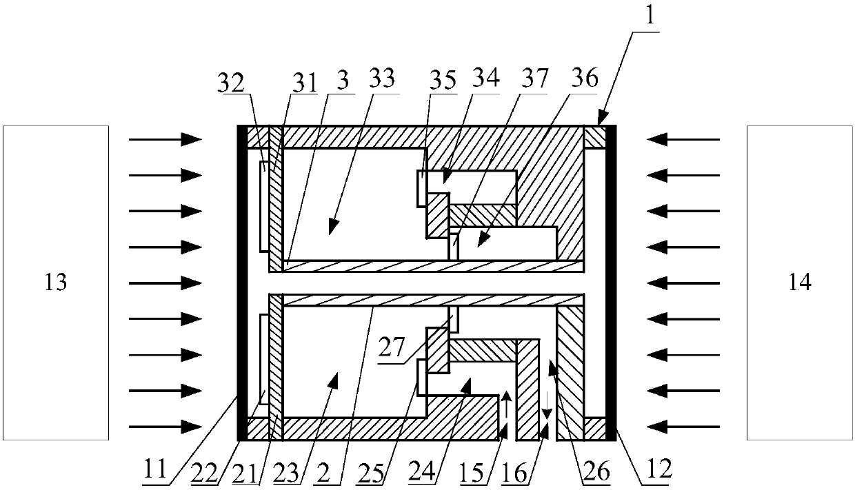
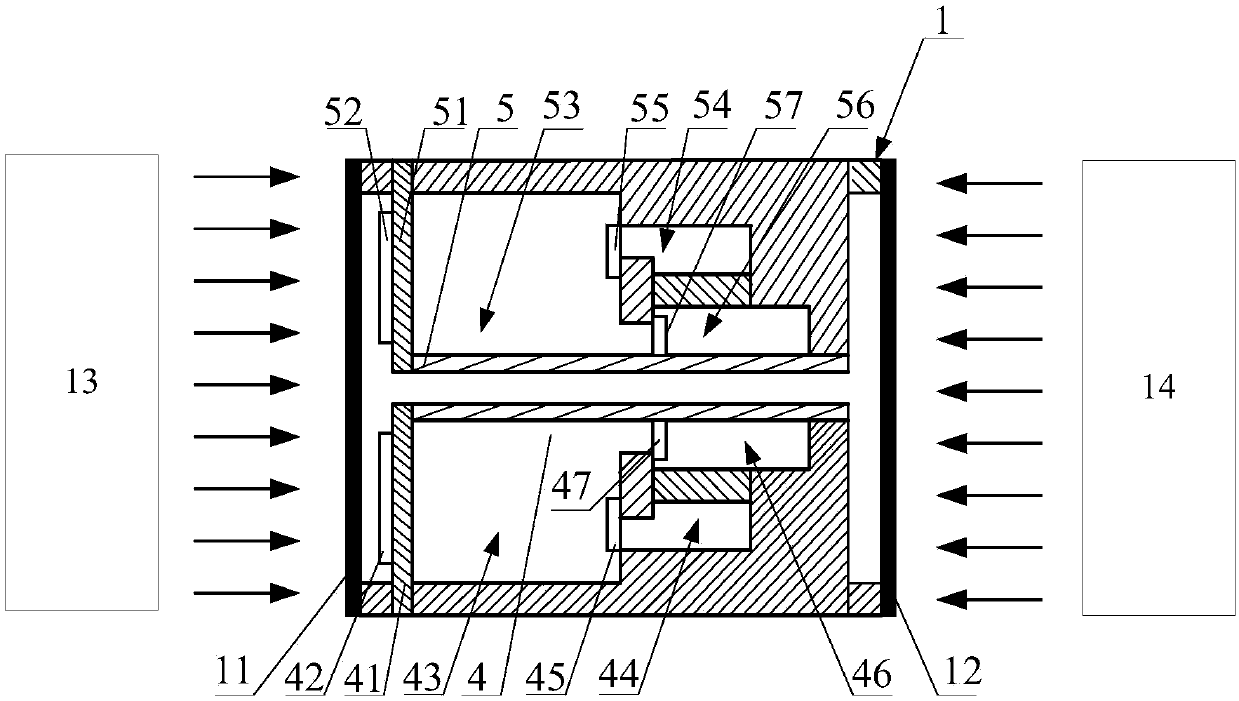
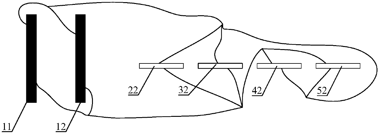
[0013] A light-controlled micropump device, comprising a pump casing 1, a first PLZT ceramic cover 11 arranged at one end of the pump casing 1 and a second PLZT ceramic cover 12 arranged at the other end of the pump casing 1, the first PLZT ceramic The outside of the cover 11 is provided with a first ultraviolet light source 13, the outside of the second PLZT ceramic cover 12 is provided with a second ultraviolet light source 14, the pump housing 1 is provided with a water inlet 15 and a water outlet 16, and the inside of the pump housing 1 is provided with The first pump body 2, the second pump body 3, the third pump body 4 and the fourth pump body 5 are uniformly distributed around the central axis of the pump casing 1, and the first pump body 2 and the second pump body 3 are related to the pump casing 1 The central axis is symmetrically dis...


PUM


Abstract

The invention discloses a light-operated micro-pump device. The device is characterized by comprising a pump casing, a first PLZT ceramic gland arranged at one end of the pump casing as well as a second PLZT ceramic gland arranged at the other end of the pump casing; a first ultraviolet light source is arranged on the outer side of the first PLZT ceramic gland; a second ultraviolet light source isarranged on the outer side of the second PLZT ceramic gland; a water inlet and a water outlet are formed in the pump casing; and a first pump body, a second pump body, a third pump body and a fourthpump body which are evenly distributed around the central axis of the pump casing are arranged in the pump casing. The device has the advantages as follows: the lagging performance between PLZT ceramic photovoltage and pump membrane deformation is avoided, and the whole structure is simple and compact; the first pump body, the second pump body, the third pump body and the fourth pump body keep theparallel-connection structure, and the first ultraviolet light source and the second ultraviolet light source irradiate alternately and periodically, so that the continuous and stable liquid flow isguaranteed, the liquid flow pulsation is small, and accurate control on liquid output is facilitated.

Description

technical field [0001] The invention relates to a micropump device, in particular to a light-controlled micropump device. Background technique [0002] The micropump is an important executive component in the microfluidic system and the core of the microfluidic system. It is widely used in the fields of micro-delivery and distribution of drugs, biochemical analysis, cooling of chip systems, and propulsion of micro-satellites. At present, the positive displacement micropump is widely used, which changes the volume of the pump body through the reciprocating change of the pump membrane, and cooperates with the inlet and outlet valves to achieve precise pumping of the liquid. The driving technology of the pump membrane is the core of the micropump technology. The performance and application of the micropump depend on different pump membrane driving technologies. At present, the driving methods of the pump membrane mainly include piezoelectric, electrostatic, electromagnetic, sha...

Claims


Application Information

Patent Timeline
Patent Type & Authority Applications(China)
IPC IPC(8): F04B43/04F04B53/10
CPCF04B43/026F04B43/028F04B43/046
Inventor 黄家瀚张崇雷牵正王骥杜建科许孟辉金育安
Owner NINGBO UNIV
Why Eureka
Try Eureka