Three-phase electricity over-voltage, under-voltage and default phase alarm circuit based on peak voltage detection

A peak voltage and alarm circuit technology, applied in the direction of measuring current/voltage, measuring device, measuring electrical variables, etc., can solve problems such as abnormal welding, poor anti-interference ability, and user loss

Pending Publication Date: 2018-03-30
HANGZHOU KAIERDA ELECTRIC WELDING MACHINE
View PDF0 Cites 4 Cited by
  • Summary
  • Abstract
  • Description
  • Claims
  • Application Information

AI Technical Summary

Problems solved by technology

[0002] During the use of the three-phase power supply welding power supply, when the power supply state has an undervoltage/phase loss fault, the welding power supply will cause failures such as a sharp drop in welding current and normal welding without alarm protection; When the voltage fails, the welding power supply will easily damage power devices, fans and other components without alarm protection, causing losses to users.
At present, most domestic electrical equipment with three-phase power supply and high-power constant voltage/constant current power supply mainly adopt the following methods for overvoltage and undervoltage alarms and phase loss alarms on the input side: a. Non-isolated resistor divider sampling, by The control system directly calculates and analyzes the sampling signa

Method used


Image

  • Three-phase electricity over-voltage, under-voltage and default phase alarm circuit based on peak voltage detection
  • Three-phase electricity over-voltage, under-voltage and default phase alarm circuit based on peak voltage detection
  • Three-phase electricity over-voltage, under-voltage and default phase alarm circuit based on peak voltage detection

Examples


Embodiment 1

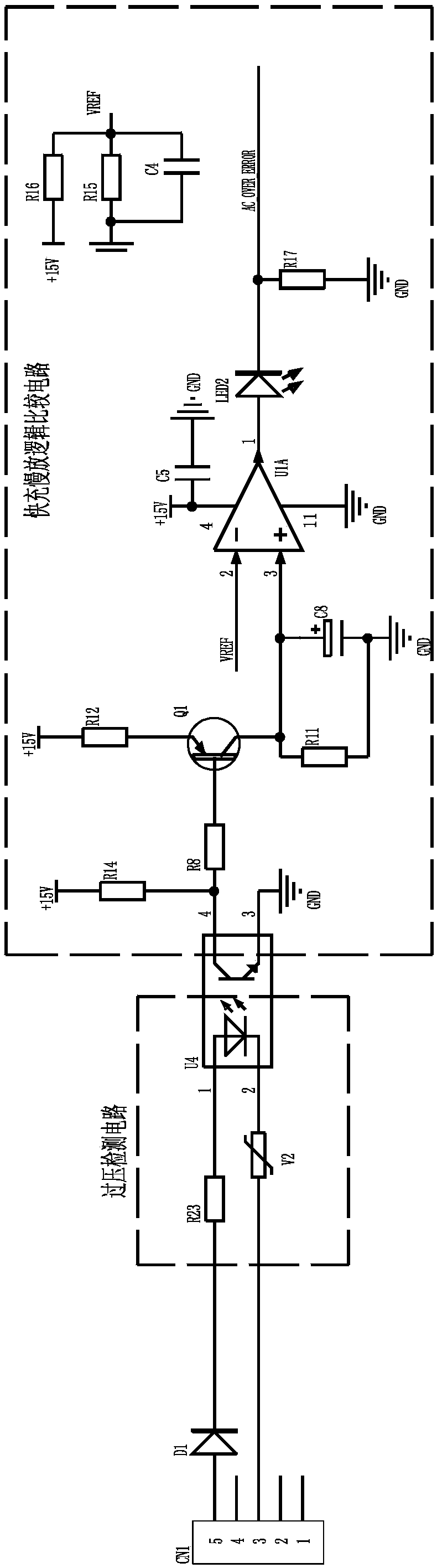
[0077] Such as figure 1 As shown, the three-phase overvoltage alarm circuit based on peak voltage detection includes:

[0078] The No. 1 diode D1 is used to lock the waveform and is connected to any phase of the three-phase power; the No. 1 diode D1 locks two phases of the three-phase power for detection to prevent the other phase of electrical signals from entering.

[0079] In the overvoltage detection circuit, one of its input terminals is connected to the first diode D1, and the other is connected to any phase of the other two phases of the three-phase power supply. When the voltage exceeds the threshold value, the output terminal of the overvoltage detection circuit is turned on; The voltage detection circuit mainly includes a current limiting resistor R23, an optocoupler U4, and a piezoresistor V2. The positive pole of the optocoupler U4 is connected to the resistor R23, and the negative pole is connected to the varistor V2. The characteristic of the varistor is that a...

Embodiment 2

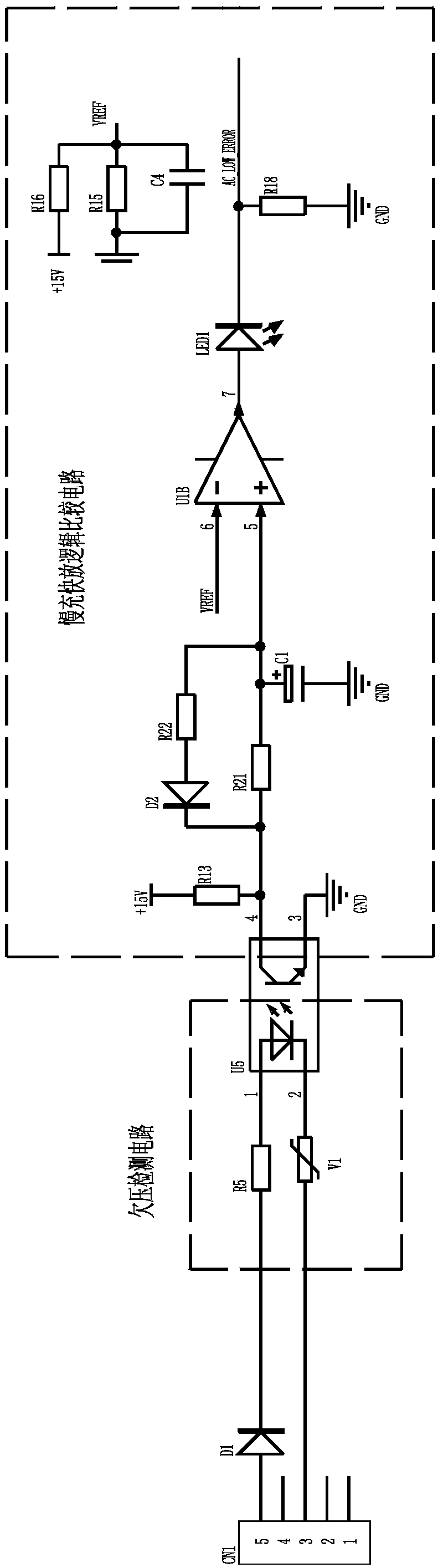
[0083] Such as figure 2 As shown, the three-phase undervoltage alarm circuit based on peak voltage detection includes:

[0084] The No. 1 diode D1 is used to lock the waveform and is connected to any phase of the three-phase power; the No. 1 diode D1 locks two phases of the three-phase power for detection to prevent the other phase of electrical signals from entering.

[0085] One of the input ends of the undervoltage detection circuit is connected to the first diode D1, and the other is connected to any phase of the other two phases of the three-phase power supply. When the voltage exceeds the threshold value, the output end of the overvoltage detection circuit is turned on. The undervoltage detection circuit mainly includes a current limiting resistor R5, an optocoupler U5, and a piezoresistor V1. The positive pole of optocoupler U5 is connected to resistor R5, and the negative pole is connected to piezoresistor V1. The principle of the undervoltage detection circuit is t...

Embodiment 3

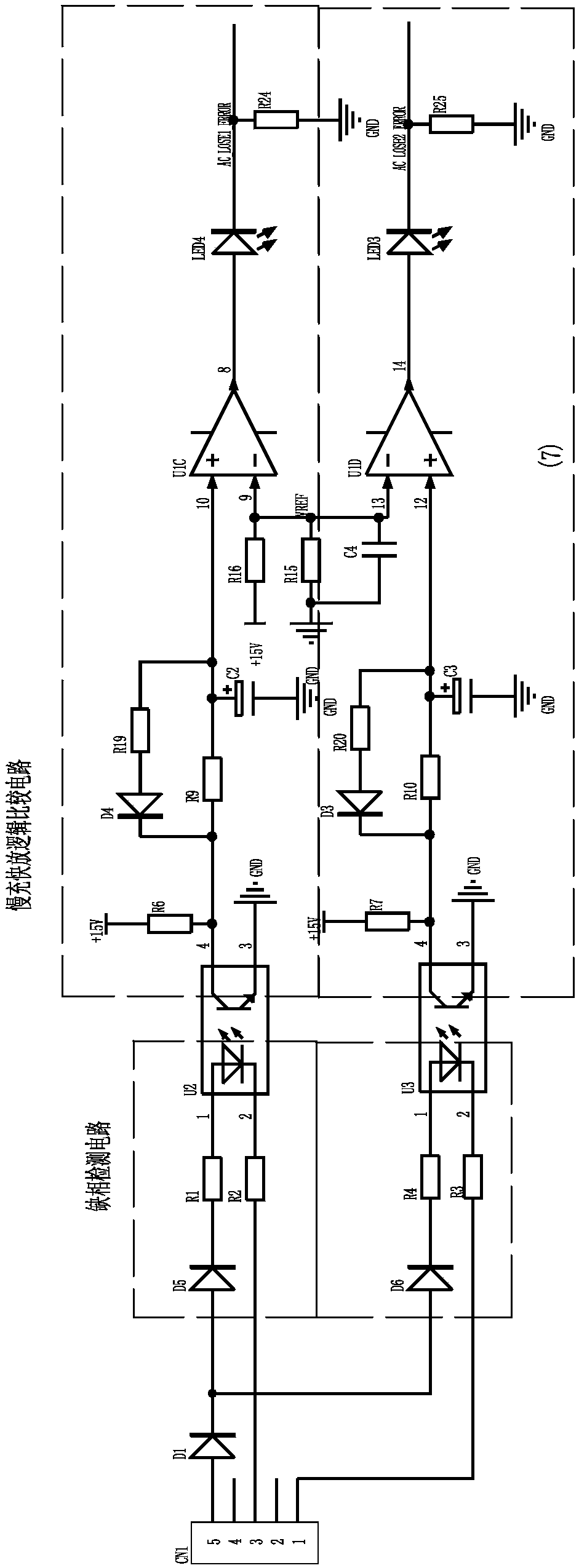
[0089] Such as image 3 As shown, the three-phase electric phase loss alarm circuit based on peak voltage detection is characterized in that it includes a diode No. 1 and two phase loss alarm branches, wherein,

[0090] The No. 1 diode D1 is used to lock the waveform and is connected to any phase of the three-phase power; the No. 1 diode D1 locks two phases of the three-phase power for detection to prevent the other phase of electrical signals from entering.

[0091] Each phase loss alarm branch includes:

[0092] Phase loss detection circuit, one of the input ends of the two phase loss detection circuits is connected to the No. 1 diode, and the other of the input ends of the two phase loss detection circuits is respectively connected to one phase of the other two phases of the three-phase power supply. When the voltage exceeds the threshold , the output terminal of the overvoltage detection circuit is turned on. The 1 / 3 / 5 pins of the plug CN1 in the phase loss detection cir...


PUM


Abstract

The invention relates to the technical field of welding power sources, in particular to a three-phase electric overvoltage, undervoltage, and lack of phase alarm circuit based on peak voltage detection, which includes a No. 1 diode connected to any phase of the three-phase electric power; the overvoltage detection circuit , one of its input terminals is connected to the No. 1 diode, and the other is connected to any phase of the other two phases of the three-phase power supply. When the voltage exceeds the threshold value, the output terminal of the overvoltage detection circuit is turned on; fast charging and slow discharging logic comparison The circuit is connected to the output terminal of the overvoltage detection circuit, and includes a fast charge and slow discharge circuit and a logic comparison circuit No. 1. When the output terminal of the overvoltage detection circuit is turned on, the energy storage element of the fast charge and slow discharge circuit is charged to generate a Voltage higher than the reference voltage, when the output terminal of the overvoltage detection circuit is closed, the energy storage element of the fast charge and slow discharge circuit discharges, but maintains a voltage higher than the reference voltage; the output terminal of the fast charge and slow discharge circuit is connected to the comparator , and compared with the reference voltage, the comparator output is connected to the alarm device.

Description

technical field [0001] The invention relates to the technical field of welding power sources, in particular to a three-phase electric overvoltage, undervoltage and phase loss alarm circuit based on peak voltage detection. Background technique [0002] During the use of the three-phase power supply welding power supply, when the power supply state has an undervoltage / phase loss fault, the welding power supply will cause failures such as a sharp drop in welding current and normal welding without alarm protection; When the voltage fails, the welding power supply will easily damage power devices, fans and other components without alarm protection, causing losses to users. At present, most domestic electrical equipment with three-phase power supply and high-power constant voltage / constant current power supply mainly adopt the following methods for overvoltage and undervoltage alarms and phase loss alarms on the input side: a. Non-isolated resistor divider sampling, by The contro...

Claims


Application Information

Patent Timeline
IPC IPC(8): G01R19/165G01R29/16
CPCG01R19/16523G01R29/16
Inventor 王青青王光辉兰照丹王丽霞
Owner HANGZHOU KAIERDA ELECTRIC WELDING MACHINE
Why Eureka
Try Eureka