A kind of array substrate and display panel

A technology of array substrates and substrates, which can be used in instruments, nonlinear optics, optics, etc., and can solve problems such as dimming of brightness, influence of display effect, loss, etc.

Active Publication Date: 2021-04-23
TCL CHINA STAR OPTOELECTRONICS TECH CO LTD
View PDF4 Cites 0 Cited by
  • Summary
  • Abstract
  • Description
  • Claims
  • Application Information

AI Technical Summary

Problems solved by technology

In the production process of LCD monitors, vertical light lines may be detected by using a solid color screen at the module stage, but in the cell lighting test, the fanout signals are the same, and there is no capacitive coupling (couple), so vertical light lines cannot be detected. Defective wires, resulting in defective products being leaked to the module, resulting in greater losses
After analysis, this phenomenon is due to the short circuit (short) caused by the poor manufacturing process of the floating electrodes in the fan-out area. When a solid color screen is formed, the adjacent fan-out signals interfere with each other due to the capacitive coupling effect, resulting in a decrease in the signal driving voltage and dimming of the brightness. , resulting in a vertical light line phenomenon
[0004] To sum up, in the manufacturing process of the liquid crystal display in the prior art, there is a short circuit due to the poor manufacturing process of the floating electrode, so that the adjacent fan-out signals in the fan-out area interfere with each other due to the capacitive coupling effect, resulting in signal drive voltage If the brightness is reduced, the brightness will become darker, resulting in the phenomenon of vertical light lines, which will affect the display effect

Method used


Image

  • A kind of array substrate and display panel
  • A kind of array substrate and display panel
  • A kind of array substrate and display panel

Examples


Embodiment Construction

[0034] The following descriptions of the various embodiments refer to the accompanying drawings to illustrate specific embodiments in which the invention may be practiced. The directional terms mentioned in the present invention, such as [top], [bottom], [front], [back], [left], [right], [inside], [outside], [side], etc., are only for reference The orientation of the attached schema. Therefore, the directional terms used are used to illustrate and understand the present invention, but not to limit the present invention. In the figures, structurally similar elements are denoted by the same reference numerals.

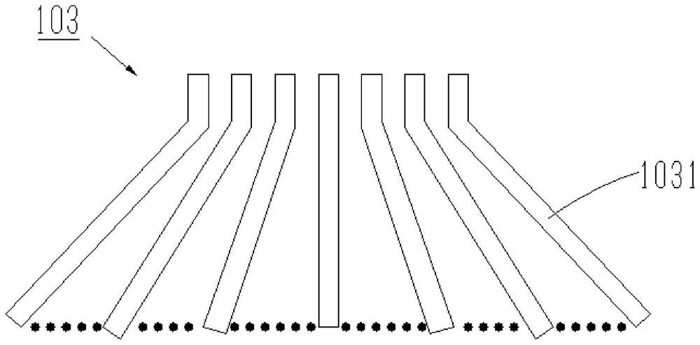
[0035] Such as Figures 6a-6b as shown, Figure 6a It is a structural schematic diagram of a strip-shaped floating electrode of a liquid crystal display in the prior art. The floating electrodes 601 are distributed in the shape of strips in the fan-out area 600 at intervals, and the fan-out area 600 is also distributed with fan-out lines. The outgoing line is separat...


PUM


Abstract

The present invention provides an array substrate and a display panel. The array substrate includes: a substrate, the substrate includes a display area and a non-display area, and the non-display area includes a fan-out area; a passivation layer is arranged on the substrate ; a pixel electrode, disposed on the passivation layer at a position corresponding to the display area; a fan-out line, disposed in the fan-out area, to be connected to a signal line disposed on the substrate; and a floating electrode , disposed on the passivation layer at a position corresponding to the fan-out area, and separated from the fan-out line; wherein, the floating electrodes include floating electrodes distributed in the fan-out area in a block shape block, and there is a gap between two adjacent floating electrode blocks.

Description

technical field [0001] The invention relates to the technical field of liquid crystal display, in particular to an array substrate and a display panel. Background technique [0002] Liquid crystal display (LCD) has become the mainstream display technology in the current market due to its advantages of high brightness, long life, wide viewing angle, and large-size display. In recent years, with the rapid development of the semiconductor display industry, LTPS, AM-OLED, Micro-LED New technologies such as LCD have threatened LCD in the field of small and medium sizes, but LCD still occupies an unshakable position in the field of large-size display due to its mature technology and manufacturing process. Therefore, improving LCD display quality, reducing product cost, improving process yield and further improving LCD technology are the main tasks of LCD when facing many new technology challenges. [0003] During the design and production process of the array substrate of the liq...

Claims


Application Information

Patent Timeline
Patent Type & Authority Patents(China)
IPC IPC(8): G02F1/1343
CPCG02F1/134309G02F1/13439
Inventor 孙立志田甜徐向阳
Owner TCL CHINA STAR OPTOELECTRONICS TECH CO LTD
Why Eureka
Try Eureka