Programmable capacitive circuit

A capacitor circuit, capacitor technology, applied in program control, instrument, computer control, etc., can solve the problems of not being able to simulate the whole process, and the range of adjusting the capacitance value is limited, so as to achieve the effect of stable capacitance value and wide adjustable range.

Inactive Publication Date: 2018-04-03
四川泛华航空仪表电器有限公司
View PDF5 Cites 0 Cited by
  • Summary
  • Abstract
  • Description
  • Claims
  • Application Information

AI Technical Summary

Problems solved by technology

[0003] The purpose of the present invention is to provide a programmable capacitor circuit, which is used to solve the problem in the prior art that the range of the capacitance analog signal for fuel computer detection is limited and the capacitance value cannot be simulated in the whole process

Method used


Image

  • Programmable capacitive circuit

Examples


Embodiment 1

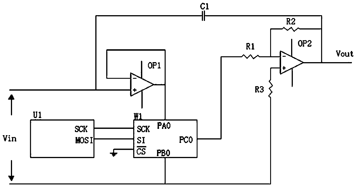
[0026] Attached figure 1 As shown, a programmable capacitor circuit includes a signal input terminal, a signal output terminal, and a first operational amplifier OP1 for voltage following and a second operational amplifier OP2 for voltage amplification connected to the signal input terminal. A digital potentiometer W1 is connected between the first operational amplifier OP1 and the second operational amplifier OP2, the digital potentiometer W1 is connected to a control chip (U1), and the signal input terminal is connected to the first operational amplifier OP1. The node is connected to the first end of the capacitor C1, and the second end of the capacitor C1 is connected to the signal output end and the output end of the second operational amplifier OP2.

[0027] working principle:

[0028] The signal Vin is input from the signal input terminal, and after the first operational amplifier OP1, the voltage follows the output, and then is divided by the digital potentiometer W1 and th...

Embodiment 2

[0030] On the basis of Example 1, combined with figure 1 As shown, the inverting input terminal of the first operational amplifier OP1 is connected to the output terminal of the first operational amplifier OP1, and the same direction input terminal of the first operational amplifier OP1 is connected to the first terminal of the signal input terminal and the capacitor C1 The output terminal of the first operational amplifier OP1 is connected to the digital potentiometer W1.

[0031] working principle:

[0032] The purpose of the voltage follower circuit composed of the first operational amplifier OP1 is to reduce signal loss and enhance the driving ability of the signal to the subsequent stage.

[0033] Further, the same direction input terminal of the second operational amplifier OP2 is connected in series with a resistor R3 and then connected to the second terminal of the signal input terminal, and the inverting input terminal of the second operational amplifier OP2 is connected in...

Embodiment 3

[0037] On the basis of Example 2, combined with figure 1 As shown, the fixed terminal of the digital potentiometer W1 is respectively connected to the output terminal of the first operational amplifier OP1 and the second terminal of the signal input terminal, and the second terminal of the signal input terminal is connected in series with the resistor R3. It is connected to the same direction input terminal of the second operational amplifier OP2, and the control pin of the digital potentiometer W1 is connected to the control chip (U1).

[0038] working principle:

[0039] In this connection mode, the adjustable end of the digital potentiometer W1 is connected to


PUM


Abstract

The invention discloses a programmable capacitive circuit which comprises a signal input end, a signal output end, an OP1 (first operational amplifier) and an OP1 (second operational amplifier), wherein the first operational amplifier OP1 is connected with the signal input end and used for voltage following, and the second operational amplifier OP2 is used for voltage amplification. A digital potentiometer W1 is connected between the first operational amplifier OP1 and the second operational amplifier OP2 and connected with a control chip, a first end of a capacitor C1 is connected on a connection node of the signal input end and the first operational amplifier OP1, and a second end of the capacitor C1 is connected with the signal output end and an output end of the second operational amplifier OP2. According to the programmable capacitive circuit, a voltage-dividing coefficient K is accurately adjusted by the control chip U1, an equivalent capacitor C is controlled by adjusting the voltage-dividing coefficient K, and the range of the equivalent capacitor is wider when a resistor R2 and a resistor R1 are adjustable resistors.

Description

Technical field [0001] The present invention relates to the technical field of automatic control, in particular, a programmable capacitor circuit. Background technique [0002] Capacitive oil level sensor is a sensor that uses the cover area between the two electrodes of the sensor to change with the change of the measured liquid level, which causes the capacitance value between the two electrodes to change to perform liquid level measurement. It is an area change type capacitive sensor. Because of its simple structure, good dynamic performance, and good temperature stability, it has been widely used in the aviation field. When detecting the fuel computer, it needs to provide the excitation signal of the capacitance sensor. The current common practice is to use a fixed capacitor for simulation. The disadvantage of this is that it can only simulate a few isolated point values ​​of the capacitor sensor, but cannot simulate the full process of the capacitor sensor, and cannot truly...

Claims


Application Information

Patent Timeline
Patent Type & Authority Applications(China)
IPC IPC(8): G05B19/042
Inventor 冷斌龙王金磊王强
Owner 四川泛华航空仪表电器有限公司
Why Eureka
Try Eureka