Waste gas suction and collection treatment equipment for chemical plant
A technology for processing equipment and chemical plants, applied in lighting and heating equipment, incinerators, chemical instruments and methods, etc., can solve the problem that the installation, use or disassembly of equipment is not convenient and fast, the absorption is not comprehensive and thorough, and the exhaust gas absorption efficiency is not enough. Low problems, to achieve the effect of convenient installation, use or disassembly, high degree of automation, and convenient operation
- Summary
- Abstract
- Description
- Claims
- Application Information
AI Technical Summary
Problems solved by technology
Method used
Image
Examples
Embodiment 1
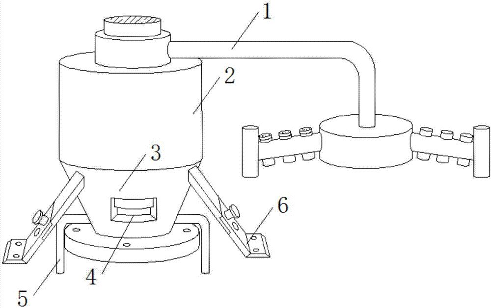
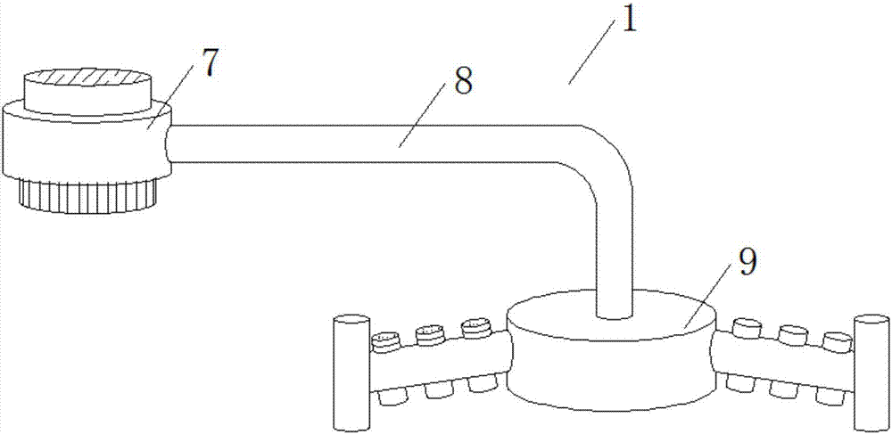
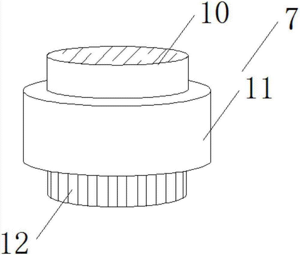
[0026] see Figure 1-5 As shown, a waste gas suction and treatment equipment used in a chemical plant includes a gas collecting pan 1, a working chamber 2 and a furnace 3. The gas collecting pan 1 is installed above the working chamber 2, and the burning furnace 3 is installed on the working chamber 2. Bottom; an air delivery tray 7 is provided at one end above the gas collection tray 1, and a first ventilation pipe 8 is arranged at one end of the air delivery tray 7, and a suction frame 9 is arranged under one end of the first ventilation pipe 8; a tray loading groove is arranged at the top of the working chamber 2 16. The transmission gear 12 below the air delivery disc 7 of the gas collecting tray 1 is connected to the inside of the loading slot 16 on the top of the working chamber 2. This device is very convenient and quick to install, use or disassemble, and a motor 17 is installed on the side of the loading slot 16 , the motor 17 continuously rotates the gas collecting d...
Embodiment 2
[0028] In addition, please continue to Figure 1-5 As shown, the difference between it and the above-mentioned embodiment is that both ends of the furnace 3 are provided with a fixing frame 6 for conveniently fixing the working chamber 2, and the working chamber 2 is installed and fixed through the fixing frame 6, so as to ensure that the working chamber 2 is more stable when in use. Stable, the two fixing frames 6 are arranged symmetrically. A blower 10 is installed on the top of the air delivery disc 7, and the exhaust gas is sucked into the gas collection disc 1 by the suction fan 10, and a transmission gear 11 is installed under the blower 10, and the motor 17 continuously rotates the gas collection disc 1 through the transmission gear 12, The fluidity of the air is improved to ensure that the device is more efficient and comprehensive in absorbing the waste gas inside the factory area. The middle part of the suction frame 9 is provided with an insertion hole 13 that matc...
PUM
 Abstract
Description
Claims
Application Information
 - R&D
- Intellectual Property
- Life Sciences
- Materials
- Tech Scout
- Unparalleled Data Quality
- Higher Quality Content
- 60% Fewer Hallucinations
Browse by: Latest US Patents, China's latest patents, Technical Efficacy Thesaurus, Application Domain, Technology Topic, Popular Technical Reports.
© 2025 PatSnap. All rights reserved.Legal|Privacy policy|Modern Slavery Act Transparency Statement|Sitemap|About US| Contact US: help@patsnap.com


