Laser cutting device and method

A laser cutting and laser technology, applied in laser welding equipment, welding equipment, metal processing equipment, etc.

Inactive Publication Date: 2018-04-06
SHANGHAI MICRO ELECTRONICS EQUIP (GRP) CO LTD
View PDF9 Cites 2 Cited by
  • Summary
  • Abstract
  • Description
  • Claims
  • Application Information

AI Technical Summary

Problems solved by technology

[0004] In the cutting of transparent materials, due to the different thickness of the cutting substrate, it is particularly i

Method used


Image

  • Laser cutting device and method
  • Laser cutting device and method
  • Laser cutting device and method

Examples


Embodiment Construction

[0023] The present invention is described in detail below in conjunction with accompanying drawing:

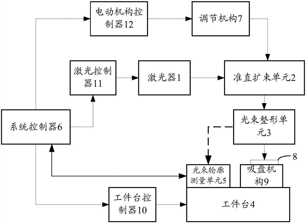
[0024] Such as figure 1 As shown, the present invention provides a laser cutting device, comprising: a laser 1, a collimator beam expander unit 2, a beam shaping unit 3 and a workpiece table 4 arranged in sequence along the optical path, and a beam profile set on the workpiece table 4 Measuring unit 5, and a system controller 6 connected to the laser 1, the collimating beam expanding unit 2, the workpiece table 4 and the beam profile measuring unit 5 respectively, and the collimating beam expanding unit 2 includes a continuously adjustable As for the mirror group, an adjustment mechanism 7 is provided between the system controller 6 and the mirror group. The workpiece table 4 is provided with a suction cup mechanism 9 to absorb the object 8 to be cut. Preferably, the detection surface of the beam profile measurement unit 5 is at the same vertical height as the surface of the ...


PUM


Abstract

The invention discloses a laser cutting device and method. The device comprises a system controller and a laser device, a collimation and beam expanding unit, a laser beam shaping unit and a workbench. A suction cup mechanism and a laser beam outline measuring unit. The vertical height of the test surface of the laser beam outline measuring unit is equal to that of the surface of the suction cup mechanism. The collimation and beam expanding unit comprises a magnification continuous adjustable shotgroup. The system controller receives laser beam energy intensity fed back by the laser beam outline measuring unit and adjusts the magnification of the shotgroup according to the thickness of a to-be-cut object. Through the laser beam outline measuring unit, detection of vertical Bessel laser beam three-dimensional energy intensity is achieved, detected data are uploaded to the system controller, the system controller controls an adjusting mechanism to adjust the incident laser beam diameterof the laser beam shaping unit according to the detected data and the thickness of the to-be-cut object, length control over cutting acting laser beams is achieved, laser energy is fully utilized, andthe machining efficiency is improved.

Description

technical field [0001] The invention relates to the technical field of semiconductor cutting, in particular to a laser cutting device and method. Background technique [0002] With the continuous expansion of the consumer electronics market, people's demand for the performance of electronic products is constantly improving, and the existing production process is facing many challenges in the production process. The demand for cutting quality and performance makes manufacturers use laser cutting technology to replace the original mechanical cutting method in the process. [0003] With the continuous maturity of ultrafast laser technology in recent years, many laser suppliers have launched industrial-grade ultrafast laser sources, which has promoted the application of laser cutting technology in the pan-semiconductor field. The reason why ultrafast lasers arouse people's widespread interest is that when light propagates in materials, the thermal diffusion depth is proportiona...

Claims


Application Information

Patent Timeline
IPC IPC(8): B23K26/046B23K26/38B23K26/08
CPCB23K26/38B23K26/046B23K26/08
Inventor 宋春峰徐文孙杰
Owner SHANGHAI MICRO ELECTRONICS EQUIP (GRP) CO LTD
Why Eureka
Try Eureka