Three-dimensional cutting device and method based on broadband laser frequency domain

A technology of cutting device and broadband light source, applied in laser welding equipment, welding equipment, metal processing equipment and other directions, can solve the problems of difficult to use camera, difficult to realize real-time detection, long calculation distance, etc., to avoid human error and operation error , The function realizes the effect of safety and reliability, and the calculation distance is short.

Active Publication Date: 2018-04-06
FOSHAN UNIVERSITY
View PDF9 Cites 4 Cited by
  • Summary
  • Abstract
  • Description
  • Claims
  • Application Information

AI Technical Summary

Problems solved by technology

[0003] Most of the focus tracking methods in the prior art can emit or reflect specific light to track the focus. Since this type of method makes the surface of the material emit light to cause scattering, and is collected by the camera for processing and judgment, it is difficult to avoid when the sample and the focus When it is too close, it is difficult to judge the positional relationship between the two due to the problem of pixels
[0004] Taking the focus tracking method as an example, the Chinese patent "Laser focus positioning system and method for locating materials at the laser focus" (publication number CN102974936A) makes the focused laser beam produce a plasma bright spot by adjusting lasers and other equipment, and controls the surface of the material Gradually approach the plasma bright spot until the bright spot image is formed, so that both the plasma bright spot and the mirror image enter the test field of the CCD microscopic imaging system, until the two are completely overlapped, and the focus is on the material surface at this time. The patented method The relative position of the focal point and the material surface is judged by the position of the plasma bright spot and the material surface in the CCD camera. Because there is a certain difference between the position of the plasma bright spot and the focal point, and the light emitted by the plasma bright spot is not received by the camera. Is a pixel point, and there may be other tiny particles in the environment that emit light with the same brightness as the plasma bright spot. These tiny particles will make it difficult to avoid errors when moving the material, and it is difficult to use the camera when the focal point enters the material from the surface of the material. To observe the cutting depth, so the patented method can only be applied in two-dimensional space
[0005] At the same time, in the prior art, the method used to detect the focus position of laser cutting is non-real-time, so it is difficult to realize real-time detection, and the method with real-time detection has higher requirements on the environment. In practical applications, when the environment meets the requirements, it needs substantially increase the cost
The real-time detection method in the prior art is cumbersome to implement, the time to calculate the distance is long, and the error is relatively large. Most of the methods for real-time tracking focus use image processing to judge the distance, so they are limited to two-dimensional space and difficult to track in three-dimensional space

Method used


Image

  • Three-dimensional cutting device and method based on broadband laser frequency domain
  • Three-dimensional cutting device and method based on broadband laser frequency domain
  • Three-dimensional cutting device and method based on broadband laser frequency domain

Examples


Embodiment Construction

[0032] The following will clearly and completely describe the technical solutions in the embodiments of the present invention with reference to the accompanying drawings in the embodiments of the present invention. Obviously, the described embodiments are only part of the embodiments of the present invention, not all of them. Based on the embodiments of the present invention, all other embodiments obtained by persons of ordinary skill in the art without creative efforts fall within the protection scope of the present invention.

[0033] It should be noted that if there is a directional indication (such as up, down, left, right, front, back...) in the embodiment of the present invention, the directional indication is only used to explain the position in a certain posture (as shown in the accompanying drawing). If the specific posture changes, the directional indication will also change accordingly.

[0034] In addition, if there are descriptions involving "first", "second" and ...


PUM


Abstract

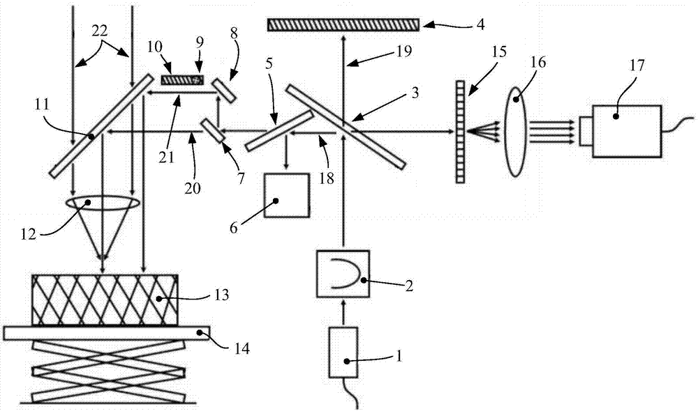
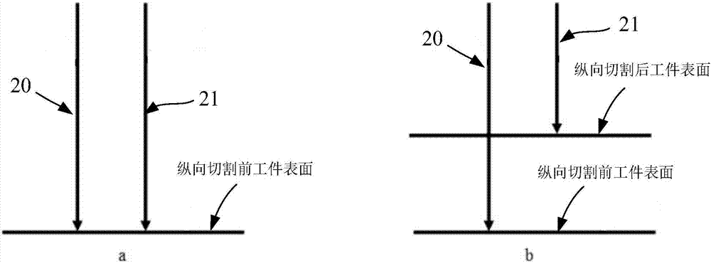
The invention discloses a three-dimensional cutting device based on a broadband laser frequency domain. Laser beams emitted by a low-coherence broadband light source pass through a first semi-reflective semi-permeable mirror and are split into a vertically-upward first laser beam and a horizontal second laser beam; a first reflective mirror is arranged above the first semi-reflective semi-permeable mirror and is perpendicular to the first laser beam; a second semi-reflective semi-permeable mirror is arranged on a light path of the second laser beam for splitting the second laser beam into a focus tracking laser beam and a longitudinal distance monitoring laser beam; a one-way photoscope is arranged on a light path of the focus tracking laser beam for reflecting the focus tracking laser beam to the top face of a workpiece; and the longitudinal distance monitoring laser beam is reflected by a second reflective mirror and the one-way photoscope sequentially to irradiate the top face of the workpiece. The invention further discloses a method using the three-dimensional cutting device based on the broadband laser frequency domain. Compared with the prior art, the three-dimensional cutting device based on the broadband laser frequency domain has the advantages that the structure is simple, control is precise and reliable, and safety and rapidness are achieved, precise reliability ofreal-time tracking of the focus position of a laser cutting machine can be improved.

Description

technical field [0001] The invention relates to the technical field of laser cutting and fixed focus, in particular to a three-dimensional cutting device and method based on broadband laser frequency domain. Background technique [0002] In the prior art, the methods used to fix the focus of laser cutting machines are mainly focusing method and tracking focus method, among which focusing methods include numerical control positioning and dotting method, oblique focus burning method, direct burning method and other methods. These methods are to cut different distances on the sample surface by laser, and then compare the thickness and size of the cut mark, and the thinner and smaller cutting position is the distance of the focal point. The focus tracking method can not only find the focus, but also display the focus position in real time, so as to clearly know the position of the focus and the object to be cut during the cutting process, so as to make appropriate adjustments. ...

Claims


Application Information

Patent Timeline
Patent Type & Authority Applications(China)
IPC IPC(8): B23K26/38B23K26/70B23K26/044
CPCB23K26/044B23K26/38B23K26/70B23K26/702
Inventor 曾亚光何镇楠孔繁培熊红莲王茗祎
Owner FOSHAN UNIVERSITY
Why Eureka
Try Eureka