Centrifugal fan

A centrifugal fan and fan blade technology, applied in mechanical equipment, machine/engine, liquid fuel engine, etc., can solve the problems of deepening the fan blade and reducing the gap between the guide ring, bearing heat, and wear of the guide ring.

Inactive Publication Date: 2021-04-02
GREE ELECTRIC APPLIANCES INC
View PDF15 Cites 0 Cited by
  • Summary
  • Abstract
  • Description
  • Claims
  • Application Information

AI Technical Summary

Problems solved by technology

[0004] The gap between the outer edge of the centrifugal fan blade and the guide ring is very small. Since the impeller is in a cantilever state, the impeller will be biased by its own gravity and the centrifugal force generated by the impeller during work, resulting in the outer end surface of the impeller and the guide ring. If the flow ring gap is too small, the flow guide ring will be worn easily, and the centrifugal fan will not work properly when the wear is serious
[0005] The bearing of the centrifugal fan is affected by the bias of the centrifugal fan, causing the shaft of the fan to not be on the horizontal line, the force on the bearing is uneven, the wear of the rolling bearing is increased, and the increase in the clearance causes the bearing to heat up and the lubricating oil to fail, thereby reducing the bearing life
[0006] The fixing bolts on the centrifugal fan are affected by the bias of the centrifugal fan, which will loosen and cause mechanical vibration, which will further deepen the gap between the fan blade and the guide ring and reduce the gap, causing wear and even safety accidents

Method used


Image

  • Centrifugal fan
  • Centrifugal fan
  • Centrifugal fan

Examples


Embodiment Construction

[0033] In order to make the technical problems, technical solutions and beneficial effects to be solved by the present application clearer, the present application will be further described in detail below in conjunction with the accompanying drawings and embodiments. It should be understood that the specific embodiments described here are only used to explain the present application, and are not intended to limit the present application.

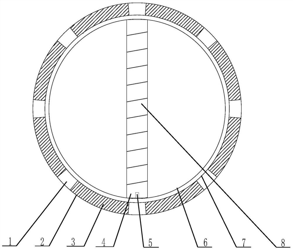
[0034] Such as figure 1 as shown,

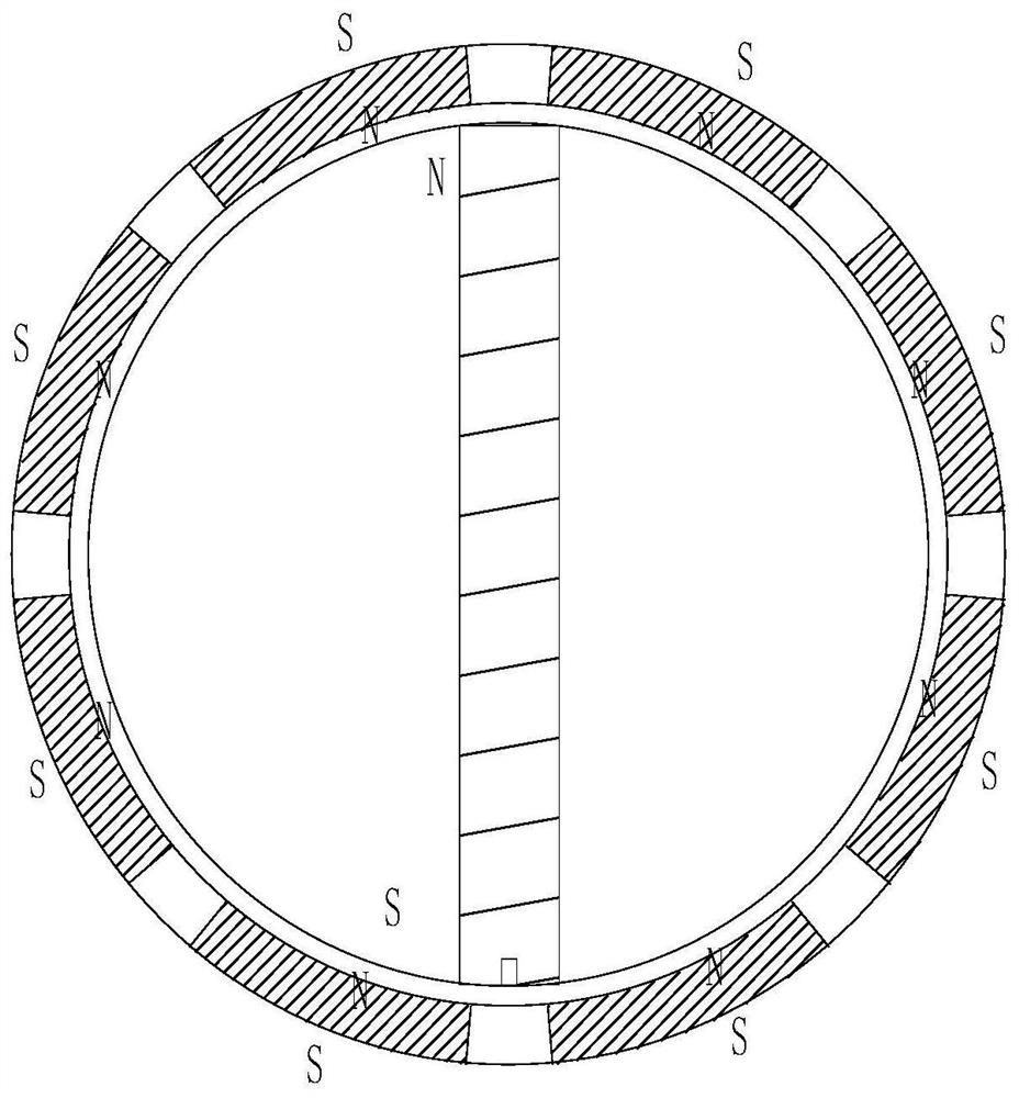
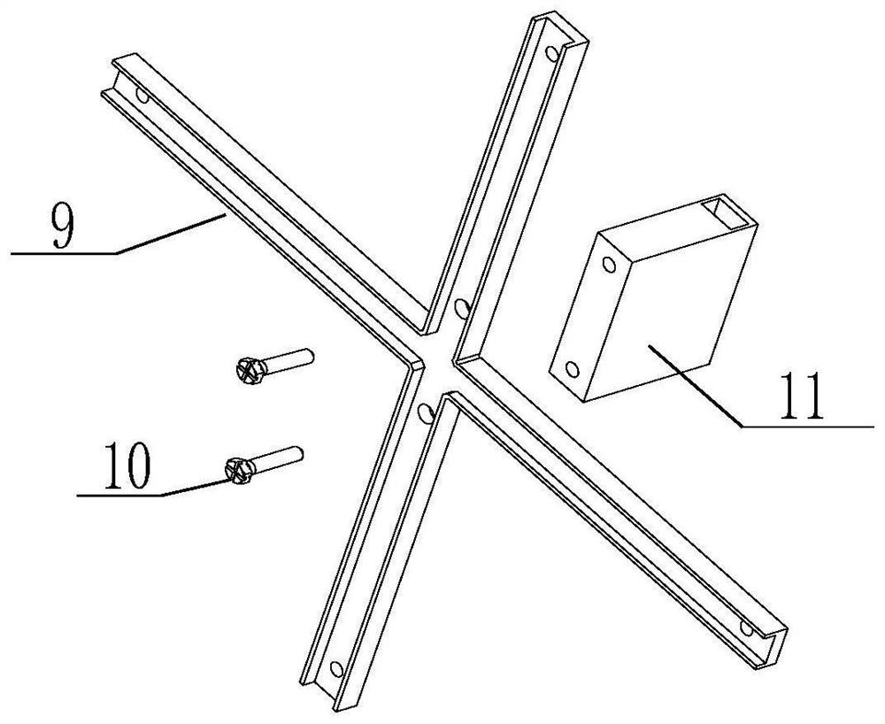
[0035] figure 1 It is a schematic structural diagram of a centrifugal wind embodiment of a machine side-mounted magnetic circuit involved in this application, which is mainly composed of a collar 2, a gasket 1, a permanent magnet 3, an electromagnet 4, a sensor 5, a guide ring 6, and a fan blade , the fan blade is not specifically shown; the spacer and the permanent magnet are evenly distributed across, and are fixed on the outer edge of the fan blade by using a collar. In the vertical direction, holes...


PUM


Abstract

The invention relates to a centrifugal fan. The centrifugal fan comprises a fan blade and a flow guide ring arranged in the fan blade, a permanent magnet structure is arranged on the outer edge of thefan blade, and a magnetic part is arranged on the flow guide ring. An upper magnetic pole of the magnetic part on the flow guide ring is the same as an inner side magnetic pole of the permanent magnet structure arranged on the outer edge of the fan blade, and a lower magnetic pole of the magnetic part on the flow guide ring is opposite to the inner side magnetic pole of the permanent magnet arranged on the outer edge of the fan blade. Through the magnetic pole arrangement mode, according to the property that poles repel each other and opposite poles attract each other, like poles repel each other between the top of an electromagnet and an inner arc surface of the permanent magnet, the fan blade is stressed upwards, opposite poles attract each other between the bottom of the electromagnetand the inner arc surface of the permanent magnet, and the fan blade is stressed upwards, the fan blade is lifted by upward resultant force, and the downward bias of an centrifugal fan impeller underthe action of gravity can be counteracted. Due to the fact that the magnetic force counteracts part of the weight of the impeller, the pressure of a motor bearing is reduced, oil lubrication failure caused by heating of the bearing is reduced, and the service life of the bearing is prolonged.

Description

technical field [0001] The invention relates to the technical field of air conditioning, in particular to a centrifugal fan. Background technique [0002] In recent years, industries such as communications and the Internet have developed rapidly, and the market demand for data centers has increased sharply. A large number of IT equipment such as servers are arranged in data centers. The high-heat components are semiconductors, which are the core components. Cooling capacity. The inter-row air conditioner is the main refrigeration equipment in the precision machine room. Its refrigeration solution is mainly aimed at high-density applications and micro-module data centers. It is close to the heat source and realizes near-end cooling, thereby reducing energy consumption. [0003] The lateral installation of the centrifugal fan in the inter-column air conditioner is relatively common. For example, the published patents CN104456904A, CN204718004U, and CN111121167A all fix the fa...

Claims


Application Information

Patent Timeline
Patent Type & Authority Applications(China)
IPC IPC(8): F04D29/30F04D29/66F04D29/44F04D27/00
CPCF04D29/30F04D29/662F04D29/666F04D29/441F04D27/00F04D27/001
Inventor 董路明古剑峰张祖鑫林海佳吴凡黎汝令
Owner GREE ELECTRIC APPLIANCES INC
Why Eureka
Try Eureka