Uplink reference signal sending method, device and system, e-Node-B and terminal

A technology of reference signal and transmission method, which is applied in the field of communication and can solve problems such as imperfect technical solutions

Active Publication Date: 2018-04-06
ZTE CORP
View PDF7 Cites 5 Cited by
  • Summary
  • Abstract
  • Description
  • Claims
  • Application Information

AI Technical Summary

Problems solved by technology

[0009] Embodiments of the present invention provide a method, device and system for sending an uplink reference signal, a base station and

Method used


Image

  • Uplink reference signal sending method, device and system, e-Node-B and terminal
  • Uplink reference signal sending method, device and system, e-Node-B and terminal
  • Uplink reference signal sending method, device and system, e-Node-B and terminal

Examples


Embodiment 1

[0277] An embodiment of the present application provides a mobile communication network (including but not limited to an LTE network). The network architecture of the network may include network-side equipment (such as a base station) and terminals. In this embodiment, a mobile communication network that can run on For the method for sending an uplink reference signal on the above network architecture, it should be noted that the operating environment of the method for sending an uplink reference signal provided in the embodiment of the present application is not limited to the above network architecture.

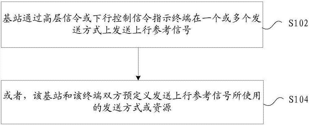
[0278] figure 1 It is a flow of a method for sending an uplink reference signal according to an embodiment of the present invention Figure 1 ,Such as figure 1 shown, including the following steps:

[0279] Step S102, the base station instructs the terminal to send uplink reference signals in one or more transmission modes through high-layer signaling or downlink control ...

specific Embodiment 1

[0367] The base station instructs the user terminal to send the uplink reference signal in one or more transmission modes through high-layer signaling or downlink control signaling, wherein the transmission mode includes at least one of the following: transmission beam, transmission antenna, and transmission sector.

[0368] Further, the information carried in the downlink control signaling includes: information for instructing the user terminal to determine the transmission mode of the uplink reference signal according to the downlink receiving mode, wherein the receiving mode includes: receiving beam, receiving antenna, and receiving sector.

[0369] Further, the user terminal determines the sending method of the uplink reference signal according to the downlink receiving method, including: taking the direction of the receiving method as a reference sending direction for sending the uplink reference signal, and the user terminal sequentially starts from the Nth direction on th...

specific Embodiment 2

[0372] The base station instructs the user terminal to send the uplink reference signal in one transmission mode or in multiple transmission modes through downlink control signaling. For example, when the value of the indication information bit carried by the downlink control signaling is 1, it indicates that the user terminal is instructed to send multiple uplink reference signals on the same transmission beam; when the value of the indication information bit carried by the downlink control signaling is When the value is 0, it indicates that the user terminal is instructed to transmit the uplink reference signal sequentially on multiple transmission beams. Alternatively, when the value of the indication information bit carried by the downlink control signaling is 0, it indicates that the user terminal is instructed to send multiple uplink reference signals on the same transmission beam; when the indication information bit carried by the downlink control signaling is set to Wh...


PUM


Abstract

The invention provides an uplink reference signal sending method, device and system, an e-Node-B and a terminal. The method comprises the steps that the e-Node-B indicates the terminal to send uplinkreference signals in one or more sending modes through a higher layer signal or a downlink control signal; or two parities: the e-Node-B and the terminal predefine sending modes or resources employedfor sending the uplink reference signals. Through application of the technical scheme, the sending modes for transmitting the uplink reference signals between the e-Node-B and the terminal are set, sothe problem that in related technologies, the technical scheme of sending the uplink reference signals is incomplete is solved, and the uplink reference signals are transmitted accurately and timely.

Description

technical field [0001] The present invention relates to the communication field, in particular, to a method, device and system for transmitting an uplink reference signal, a base station and a terminal. Background technique [0002] In related technologies, in Long Term Evolution (LTE for short), a Physical Downlink Control Channel (PDCCH for short) is used to carry uplink and downlink scheduling information and uplink power control information. Downlink Control Information (DCI for short) format (format) is divided into DCI format 0, 1, 1A, 1B, 1C, 1D, 2, 2A, 3, 3A, etc., and later evolved to LTE-A Release 12 ( In LTE-A version 12), DCI formats 2B, 2C, and 2D are added to support a variety of different applications and transmission modes. The base station (e-Node-B, referred to as eNB) can configure the terminal equipment (User Equipment, referred to as UE) through downlink control information, or the terminal equipment accepts the configuration of higher layers (higher la...

Claims


Application Information

Patent Timeline
IPC IPC(8): H04B7/06H04L27/26
CPCH04B7/0626H04L27/261H04B7/0695H04L5/0023H04B7/088H04L5/0051H04L5/0091H04W72/23
Inventor 王瑜新鲁照华蒋创新陈艺戬李儒岳吴昊
Owner ZTE CORP
Why Eureka
Try Eureka