Hydraulic cylinder body forging device

A technology of hydraulic cylinders and forging machines, which is applied in the direction of piercing presses, forging presses, etc., and can solve the problems of large impact force and inaccurate processing dimensions, so as to reduce the impact force, avoid deformation of parts, and stabilize power transmission Effect

Active Publication Date: 2018-04-10
重庆博创知识产权运营有限公司
View PDF7 Cites 0 Cited by
  • Summary
  • Abstract
  • Description
  • Claims
  • Application Information

AI Technical Summary

Problems solved by technology

[0006] The purpose of the present invention is to provide a hydraulic cylinder block forging machine to

Method used


Image

  • Hydraulic cylinder body forging device
  • Hydraulic cylinder body forging device
  • Hydraulic cylinder body forging device

Examples


Embodiment 1

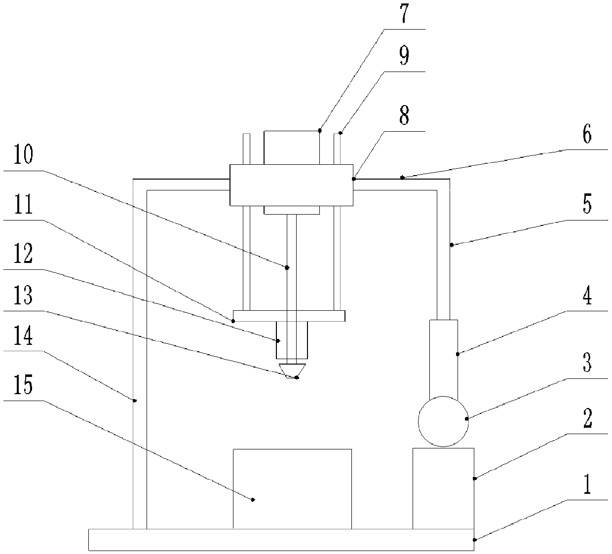
[0022] like figure 1 As described above, the hydraulic cylinder block forging machine of the present invention includes: a base 1, a guide rail 14 is installed on the left end of the base 1, a hydraulic oil tank 2 is installed on the right end, a clamping device 15 is installed in the middle of the base 1, and a Oil pump 3 and telescopic rod 4, support rod 5 is installed on the upper end of telescopic rod 4, cross beam 6 is installed between support rod 5 and guide rail 14, cross beam 6 and guide rail 14 sliding connection, support frame 8 is installed on cross beam 6, stepping Motor 7 is installed on the support frame 8, and the bottom of the rotating shaft 10 of stepping motor 7 is equipped with support plate 11, and cutter head 13 is installed on rotating shaft 10 ends, and cutter head 13 is slidably connected on the rotating shaft 10 of stepping motor 7, in A seamless steel pipe 12 is installed between the cutter head 13 and the support plate 11, and the seamless steel pip...

Embodiment 2

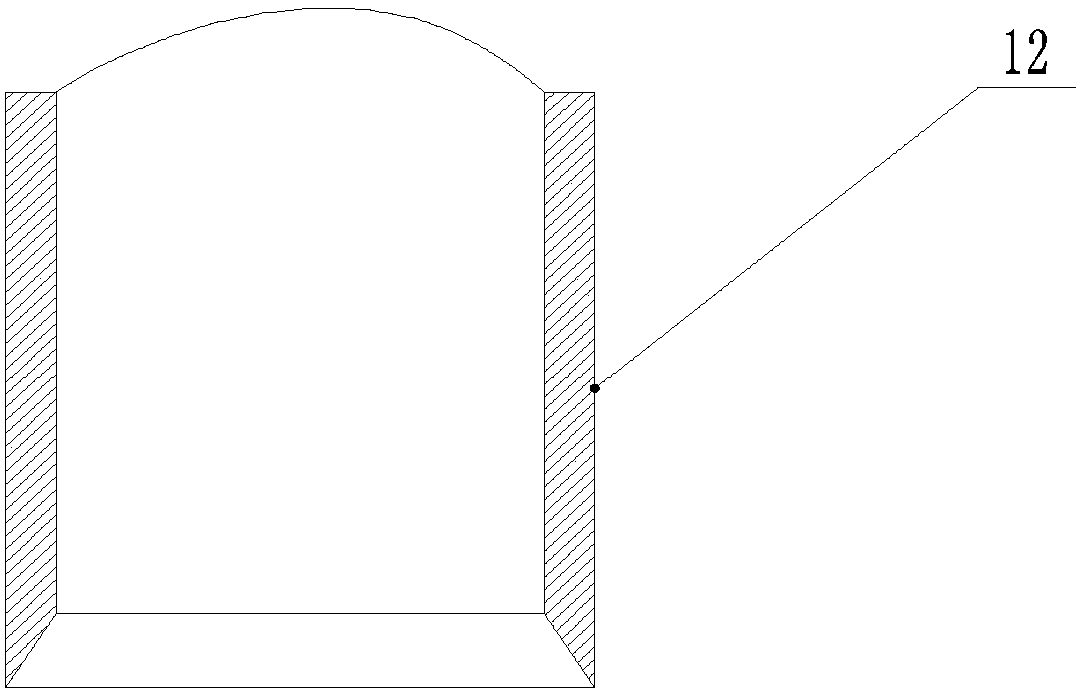
[0025] like figure 2 As shown, on the basis of Embodiment 1, the punching end of the seamless steel pipe 12 is processed into a wedge shape, which can reduce resistance when punching parts, and facilitate punching off the convex part on the hole wall.

Embodiment 3

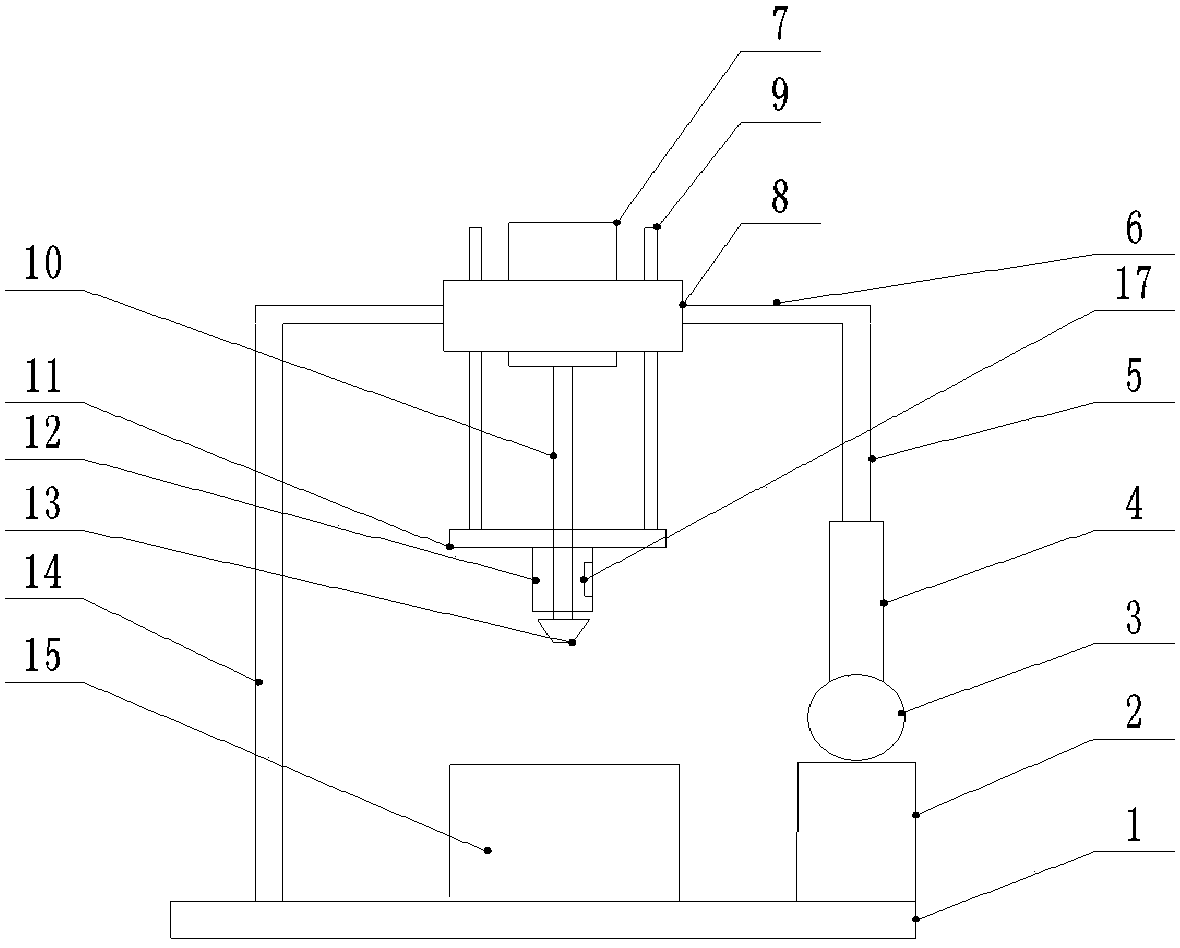
[0027] like image 3 As shown, on the basis of Embodiment 2, a bar magnet 17 is fixedly installed on the inner wall of the seamless steel pipe 12, and when the seamless steel pipe 12 is punched, the bar magnet 17 can absorb debris in the hole to Around the seamless steel pipe 12, when the expansion rod 4 rises, the debris can be taken out of the punched hole, which is convenient for cleaning the debris; bearings are installed at the junction of the crossbeam 6 and the guide rail 14, so that the resistance is reduced when the crossbeam 6 moves up and down.


PUM


Abstract

The invention relates to the technical field of forging equipment and particularly discloses a hydraulic cylinder forging device. The hydraulic cylinder forging device comprises a base, a hydraulic telescopic mechanism is arranged at one end of the base, a guide rail is arranged at the other end of the base, and a clamping device is arranged in the middle of the base. The hydraulic telescopic mechanism comprises a hydraulic oil tank, an oil pump and a telescopic rod. The hydraulic oil tank, the oil pump, the telescopic rod and a supporting rod are sequentially arranged on the upper portion ofthe base, a crossbeam is arranged between the supporting rod and the guide rail, a supporting frame and a stepping motor are sequentially arranged on the crossbeam, and a rotating shaft of the stepping motor is sequentially provided with a supporting plate and a tool bit. The supporting plate is in threaded connection with the rotating shaft, guide rods are arranged between the supporting plate and the supporting frame, a seamless steel pipe is arranged between the supporting plate and the tool bit, the rotating shaft is sleeved with the seamless steel pipe, and the tool bit corresponds to theclamping device. The hydraulic cylinder forging device is mainly used for forging hydraulic cylinder bodies, and the problem that machining sizes are not accurate in the forging process is solved.

Description

technical field [0001] The invention belongs to the technical field of forging equipment, and specifically discloses a hydraulic cylinder block forging machine. Background technique [0002] A variety of mechanical parts can be forged through forging equipment, which is more efficient than machine tools, and the forged parts are integrally formed, with high mechanical strength and long service life. [0003] However, in the forging process, the forging machines used generally have complex structures, many parts, and high manufacturing costs; the residual skin on the surface of the mechanical parts after forging cannot be removed, which affects the quality of the parts; there are many steps in the forging operation, which brings a lot of inconvenience to the operator. [0004] In view of the above problems, the patent with the notification number of CN101554639B discloses a hydraulic cylinder block forging machine, which includes a main frame, a pressurizing device is arrange...

Claims


Application Information

Patent Timeline
IPC IPC(8): B21J9/04B21J9/12
CPCB21J9/04B21J9/12
Inventor 谷山品
Owner 重庆博创知识产权运营有限公司
Why Eureka
Try Eureka