
A flow-distributing and noise-reducing curved surface structure for multi-blade centrifugal fans

A technology with a curved surface structure and a centrifugal fan, which is used in the components, applications, and household stoves of pumping devices for elastic fluids, which can solve problems such as loud noise, affecting the overall performance of the range hood, and turbulent flow at the bottom of the volute. , to achieve the effect of reducing operating noise, avoiding impact, and increasing air volume

Active Publication Date: 2020-07-28
XI AN JIAOTONG UNIV
View PDF7 Cites 0 Cited by
  • Summary
  • Abstract
  • Description
  • Claims
  • Application Information

AI Technical Summary

Problems solved by technology

[0003] However, the oil fume entering the air intake channel from the fume collecting hood will directly hit the bottom curved surface of the multi-wing fan volute, resulting in severe turbulent flow at the bottom of the volute, forming a stagnation area, and the oil fume cannot smoothly enter the range hood, resulting in Surface flow separation occurs between the oil fume flow and the wall of the air intake channel, which affects the overall performance of the range hood and generates a lot of noise

Method used


Image

  • A flow-distributing and noise-reducing curved surface structure for multi-blade centrifugal fans
  • A flow-distributing and noise-reducing curved surface structure for multi-blade centrifugal fans
  • A flow-distributing and noise-reducing curved surface structure for multi-blade centrifugal fans

Examples


Embodiment Construction

[0034] In describing the present invention, it is to be understood that the terms "centre", "upper", "lower", "front", "rear", "left", "right", "vertical", "horizontal" etc. The indicated orientation or positional relationship is based on the orientation or positional relationship shown in the drawings, and is only for the convenience of describing the present invention and simplifying the description, rather than indicating or implying that the referred device or element must have a specific orientation, or in a specific orientation. construction and operation, therefore, should not be construed as limiting the invention. In addition, the terms "first" and "second" are used for descriptive purposes only, and cannot be interpreted as indicating or implying relative importance or implicitly specifying the quantity of indicated technical features.

[0035] In the description of the present invention, it should be noted that unless otherwise specified and limited, the terms "inst...


PUM


Abstract

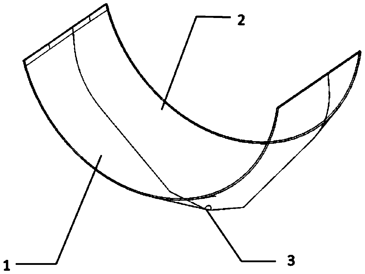
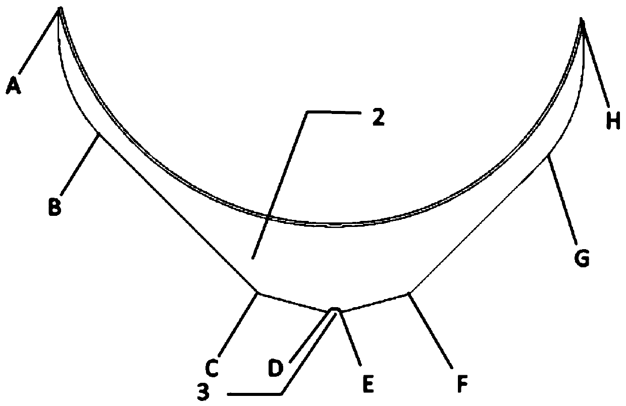
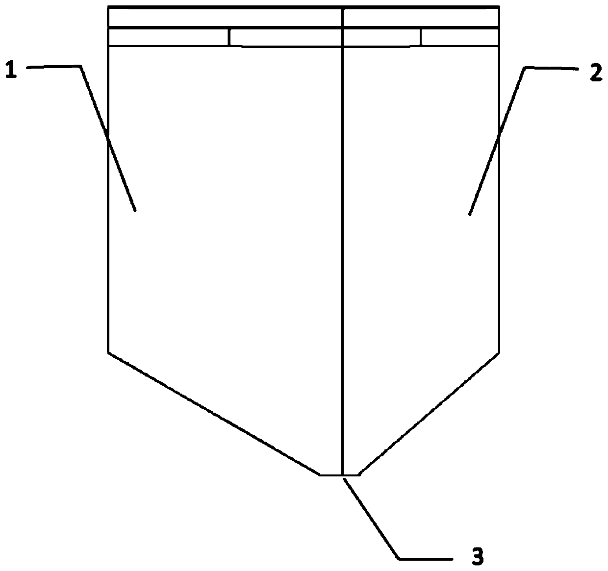
The invention discloses a flow-dividing noise-reduction hook face structure used for a multi-wing centrifugal fan. The hook face structure is installed under the multi-wing centrifugal fan, left and right boundaries are connected with the lower portion of a volute of the multi-wing centrifugal fan in an extractor hood, the hook face structure comprises a front hook face and a back hook face, an angle is formed between the front hook face and the back hook face, the front hook face is arranged on the side close to a motor, and the back hook face is arranged on the side far away from the motor;and front and back boundaries of the front hook face and the back hook face are coincident with an outer wrapping line of the volute, the front hook face and the back hook face are asymmetrically arranged on the left side and the right side of the hook face structure, and intersecting lines of the front hook face and the back hook face are connected to form a downward sinking shape, and an oil guide hole is formed in the bottom of the hook face structure. By means of the flow-dividing noise-reduction hook face structure, direct impact of lampblack to the lower side of the volute can be avoided, and the running noise of the extractor hood is greatly reduced.

Description

technical field [0001] The invention belongs to the technical field of fluid machinery, and in particular relates to a flow diversion and noise reduction curved surface structure installed at the lower part of a multi-blade centrifugal fan. Background technique [0002] The range hood is one of the essential equipment for kitchen appliances. At present, the range hood is mainly composed of a box body and a multi-blade centrifugal fan. The box body includes a smoke collecting hood and an air intake box, and the multi-blade centrifugal fan includes a volute, a multi-blade impeller and a motor driving the impeller to rotate. When the range hood is working, the motor drives the multi-wing impeller to rotate, so that the impeller inlet forms a negative pressure area, generating suction, so that the external oil fume enters the fume collection hood, and then enters the side inlet formed by the front and rear sides of the volute and the air intake box. The gas channel is discharg...

Claims


Application Information

Patent Timeline
Patent Type & Authority Patents(China)
IPC IPC(8): F04D29/44F04D29/68F24C15/20
CPCF04D29/441F04D29/681F24C15/20
Inventor 刘小民胡付佳魏铭李典
Owner XI AN JIAOTONG UNIV
Learn More