Laser Stitch Welding Seam Concavity Detection Method Based on Line Structured Light Sensor

A line-structured light and detection method technology, which is applied in the direction of instruments, measuring devices, and optical devices, can solve the problems of inability to meet the production and inspection cycle and low detection efficiency, and achieve low requirements for processing units and good robustness , solving the simple effect

Active Publication Date: 2020-04-10
CRRC CHANGCHUN RAILWAY VEHICLES CO LTD
View PDF11 Cites 0 Cited by
  • Summary
  • Abstract
  • Description
  • Claims
  • Application Information

AI Technical Summary

Problems solved by technology

[0005] In order to solve the problems of low detection efficiency in the existing laser stitch welding seam detection technology and the inability to meet the needs of the production and inspection cycle, the present invention provides a method for detecting the concave amount of the laser stitch welding seam based on a line structured light sensor

Method used


Image

  • Laser Stitch Welding Seam Concavity Detection Method Based on Line Structured Light Sensor
  • Laser Stitch Welding Seam Concavity Detection Method Based on Line Structured Light Sensor
  • Laser Stitch Welding Seam Concavity Detection Method Based on Line Structured Light Sensor

Examples


specific Embodiment approach 1

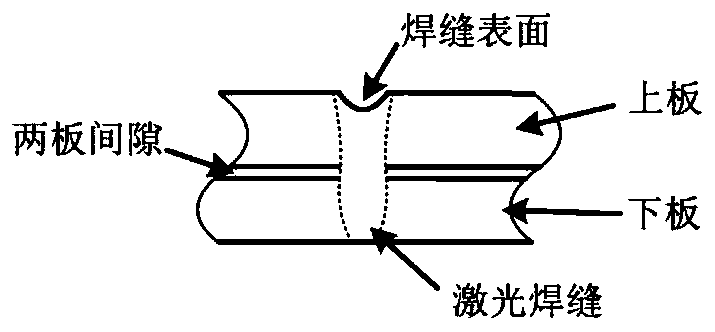
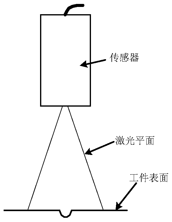
[0032] Specific implementation mode 1. Combination Figure 1 to Figure 6 Describe this embodiment, based on the detection method of the concave amount of the laser stitch welding seam based on the line structured light sensor, when there is a gap between the two plates of the stitch welding joint ( figure 1 As shown), the surface of the weld will be concave, and the amount of the concave will directly affect the performance of the welded joint; figure 2 It is a schematic diagram of scanning with a line-structured light sensor. The laser line is perpendicular to the direction of the weld seam when the optical plane sensor is scanned by the tooling. Its concave amount h( image 3 ) is defined as the vertical distance from the workpiece surface to the bottom of the weld groove.

[0033] In actual measurement, it may appear as Figure 4 , Figure 5 The situation shown should be taken into consideration when designing the detection algorithm. Figure 4 It is shown that the su...

specific Embodiment approach 2

[0050] Specific Embodiment 2. This embodiment is an embodiment of the laser stitch welding seam concave detection method based on the line structured light sensor described in the specific embodiment 1: at a certain moment, a certain laser stitch welding is measured by the line structured light sensor Weld seam, the coordinates of the obtained feature points are P 1 (5,0),P 2 (15,-1),P 3 (15.5,-1.63),P 4 (16,-1), P 5 (26.01,-0.12), the feature point coordinates contain Figure 4 Problems where the surface of the workpiece shown is not parallel to the lower surface of the sensor, and Figure 5 For the non-parallel problem of workpiece surfaces on both sides of the stitch welding seam shown, according to the aforementioned content of the invention (in mm), then

[0051]

[0052]

[0053]

[0054]

[0055]

[0056] h=-0.61

[0057] According to the algorithm, it can be calculated that the concave amount of the laser stitch welding seam at the detection pos...


PUM


Abstract

The invention discloses a method for detecting the depression amount of a laser stitch welding seam based on a line structured light sensor, relates to the technical field of laser stitch welding seamdetection, and solves the problem that the existing laser stitch welding seam detection technology has a low detection efficiency and cannot meet the requirements of the production delivery-check cycle and the like. A line structured light sensor is used to measure feature points P1, P2,..., P5 of a surface shape of a laser stitch welding seam; and obtained measurement points are represented by aline segment P1P2 and a line segment P4P5, coordinates of the feature points P1, P2, P4 and P5 are substituted into formulas f1(x) and f2(x), an intersection point Q1 between the line segment P1P2 and the line segment P4P5 is solved, a midpoint Q2 of the line segment P2P4 is solved based on the feature points P2 and P4, coordinates of a midpoint Q3 of a line segment Q1Q2 and coordinates of the feature point P3 are solved, and the depression amount h of the laser stitch welding seam to be detected is solved. The method can replace a traditional dial indicator measurement method so as to have obvious advantages in detection efficiency, detection accuracy, and operation intensity, and also facilitates the miniaturization and integration of detection equipment.

Description

technical field [0001] The invention relates to the technical field of laser stitch welding seam detection, in particular to a laser stitch welding seam concavity detection method based on a line structured light sensor. Background technique [0002] Laser lap welding joints are a common joint type in new rail passenger car structures. Due to the influence of assembly gaps, the problem of weld surface depression often occurs. The research shows that for a certain plate thickness combination, the load-bearing requirements can be met if the weld sag does not exceed a certain threshold. Therefore, the weld sag detection of laser stitch welding can be used as an important basis for evaluating weld performance. one. However, there is no accurate, fast, and convenient detection method at present, and the detection efficiency of the traditional dial gauge measurement method is low, and it is difficult to meet the needs of the production and inspection cycle. Therefore, it is nece...

Claims


Application Information

Patent Timeline
Patent Type & Authority Patents(China)
IPC IPC(8): G01B11/30
CPCG01B11/30
Inventor 李凯何广忠刘立国王春生
Owner CRRC CHANGCHUN RAILWAY VEHICLES CO LTD
Why Eureka
Try Eureka