Glue centrifugal de-foaming device for electronic processing
A centrifugal defoaming and glue technology, which is applied to the surface coating liquid device, liquid degassing, separation methods, etc., can solve the problems of low defoaming efficiency, poor glue flow effect, and affecting the dispensing effect. To achieve the effect of improving efficiency and effectiveness
- Summary
- Abstract
- Description
- Claims
- Application Information
AI Technical Summary
Problems solved by technology
Method used
Image
Examples
Embodiment 1
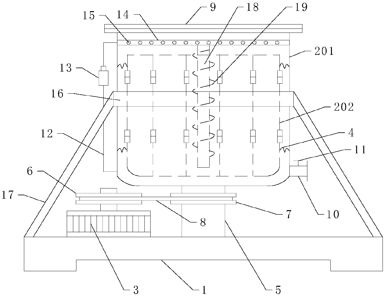
[0017] Such as figure 1 As shown, in the electronic processing glue centrifugal defoaming device of the present embodiment, a centrifugal cylinder is arranged above the base 1, and the centrifugal cylinder includes an outer cylinder 201 and an inner cylinder 202, and the top of the outer cylinder is provided with a glue adding port. A cover plate 9 is provided at the liquid addition port, a glue discharge port 10 is provided at the bottom of the outer cylinder, and a valve 11 is provided at the glue discharge port. The side walls of the blocks are spliced by hinged arc-shaped plates in turn. The arc-shaped plates are connected to the side wall of the outer cylinder through the spring 4. The outer cylinder is connected to the base through the rotating shaft 5. The rotating shaft is driven to rotate by the motor 3. Specifically, The rotating shaft is provided with a driven pulley 7 that rotates synchronously with the rotating shaft, and the output shaft of the motor is provide...
Embodiment 2
[0019] Compared with Embodiment 1, this embodiment is different in that: a circulation pipe 12 connecting the bottom and top of the outer cylinder is provided on the side wall of the outer cylinder, a circulation pump 13 is provided on the circulation pipe, and the outer cylinder is close to The position of the top is straddled with a glue spray pipe 14 communicated with the circulation pipe, and the side wall of the glue spray pipe is evenly provided with a plurality of glue spray holes, and glue spray nozzles 15 are arranged in the glue spray holes. . The circulation pump works, and the glue is pumped from the bottom of the centrifugal cylinder to the top, and sprayed out through the glue spray nozzle, thereby improving the fluidity and dispersion of the glue, and further improving the efficiency and effect of defoaming.
Embodiment 3
[0021] Compared with Embodiment 1 and Embodiment 2, the difference of this embodiment is that a vertical shaft 18 is arranged in the center of the glue spraying pipe, and a spiral stirring blade 19 extending axially along the vertical shaft is arranged on the vertical shaft. During the centrifugal defoaming process of the glue, due to the viscosity of the glue, the rotation of the glue will be slower than that of the centrifugal cylinder, and the vertical shaft and the centrifugal cylinder will rotate synchronously, so the spiral stirring blade will have a stirring effect on the glue, thereby increasing the viscosity of the glue. Centrifugal action is beneficial to the defoaming of glue.
PUM
 Abstract
Description
Claims
Application Information
 - R&D
- Intellectual Property
- Life Sciences
- Materials
- Tech Scout
- Unparalleled Data Quality
- Higher Quality Content
- 60% Fewer Hallucinations
Browse by: Latest US Patents, China's latest patents, Technical Efficacy Thesaurus, Application Domain, Technology Topic, Popular Technical Reports.
© 2025 PatSnap. All rights reserved.Legal|Privacy policy|Modern Slavery Act Transparency Statement|Sitemap|About US| Contact US: help@patsnap.com

