Liquid crystal panel defoaming equipment

A liquid crystal panel, panel technology, applied in nonlinear optics, instruments, optics, etc., can solve the problems of lack of pertinence, long boosting time in confined spaces, etc., and achieve the effect of high defoaming efficiency and no air tightness requirements

Inactive Publication Date: 2015-03-11
HEFEI XINSHENG OPTOELECTRONICS TECH CO LTD +1
View PDF3 Cites 5 Cited by
  • Summary
  • Abstract
  • Description
  • Claims
  • Application Information

AI Technical Summary

Problems solved by technology

[0004] The existing pressurization and defoaming device is a closed Chamber (closed) type of pressurization. The pressurization time in the closed space is long, and the entire space is constant pressure. The edge bubbles corresponding to the high frequency of attached bubbles are not targeted. Keeping Time (hold high pressure time) long

Method used


Image

  • Liquid crystal panel defoaming equipment
  • Liquid crystal panel defoaming equipment
  • Liquid crystal panel defoaming equipment

Examples


Embodiment Construction

[0036] The features and principles of the present invention will be described in detail below in conjunction with the accompanying drawings, and the examples given are only used to explain the present invention, not to limit the protection scope of the present invention.

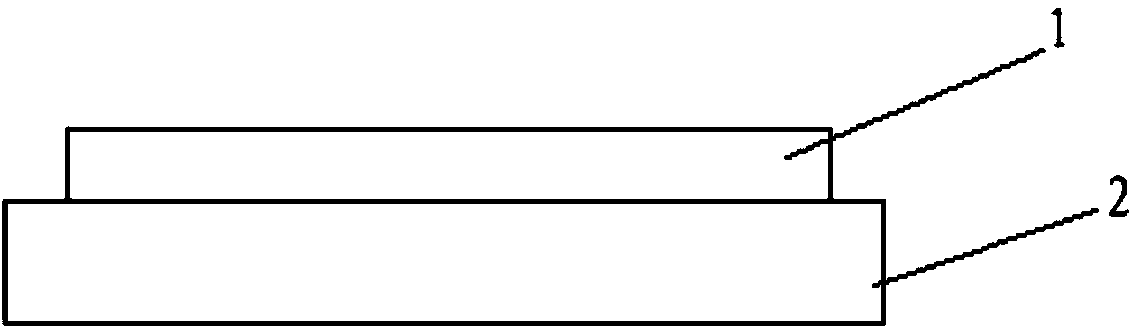
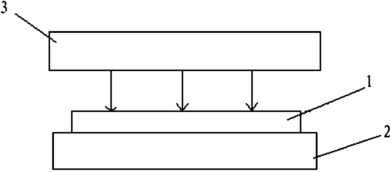
[0037] Such as figure 1 and figure 2 As shown, the present embodiment provides a liquid crystal panel defoaming equipment, including:

[0038] Adsorption unit 2 for adsorption panel 1;

[0039] The pressurizing unit 3 is used to provide compressed gas to act on the surface of the panel 1 for defoaming.

[0040] In an open environment, there is no need for airtightness requirements, the structure of the degassing equipment is simple, the service life is long, and the maintenance is convenient; the compressed gas is used to directly act on the surface of the panel for degassing treatment, which greatly shortens the boosting time. Such as figure 2 as shown, figure 2 The middle arrow is the flow directio...


PUM


Abstract

The invention relates to liquid crystal panel defoaming equipment which comprises an adsorption unit for adsorbing a panel, and a pressurizing unit for providing compressed air which acts on the surface of the panel to realize defoaming. The liquid crystal panel defoaming equipment has the beneficial effects of opened type high-pressure defoaming, no airtight requirement and high defoaming efficiency.

Description

technical field [0001] The invention relates to the field of display technology, in particular to a defoaming device for a liquid crystal panel. Background technique [0002] TFT-LCD (Thin Film Transistor Liquid Crystal Display, Thin Film Transistor Liquid Crystal Display), as a flat panel display device, has become more and more popular due to its small size, low power consumption, no radiation and relatively low production cost. It is widely used in the field of high-performance display. [0003] The existing TFT-LCD manufacturing process mainly includes four stages, which are color filter preparation, Array (array substrate manufacturing) process, Cell (liquid crystal box preparation) process and Module (module assembly) process. Among them, in the Module process, it is necessary to perform degassing treatment on the liquid crystal panel on which the polarizer has been attached, so as to eliminate or reduce the effect of attaching air bubbles, and finally improve the pro...

Claims


Application Information

Patent Timeline
Patent Type & Authority Applications(China)
IPC IPC(8): G02F1/13
CPCG02F1/1303
Inventor 顾楠轩郑友许安龙
Owner HEFEI XINSHENG OPTOELECTRONICS TECH CO LTD
Why Eureka
Try Eureka