Portable inner cavity micro-hole drilling machining device

A processing device, portable technology, applied in the direction of positioning device, boring/drilling, metal processing equipment, etc., to achieve the effect of simple operation, convenient operation and improved processing efficiency

Active Publication Date: 2018-04-13
HENAN POLYTECHNIC UNIV
View PDF6 Cites 3 Cited by
  • Summary
  • Abstract
  • Description
  • Claims
  • Application Information

AI Technical Summary

Problems solved by technology

[0004] In order to solve the deficiencies in the prior art, the present invention provides a portable inner cavity microhole drilling processing device, which can effectively solve t

Method used


Image

  • Portable inner cavity micro-hole drilling machining device
  • Portable inner cavity micro-hole drilling machining device
  • Portable inner cavity micro-hole drilling machining device

Examples


Embodiment Construction

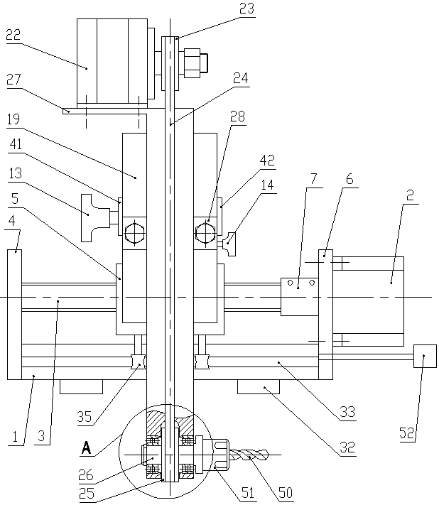
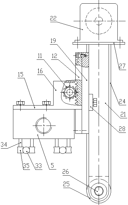
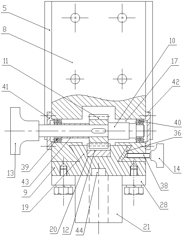
[0029] Such as Figure 1 to Figure 7 shown in figure 1 The left side of the left side is the left side of the present invention. The portable inner cavity microhole drilling processing device of the present invention includes a fixed base 1, a feeding mechanism, a lifting mechanism, a tool transmission mechanism and a detachable tool structure;

[0030] The fixed base 1 is arranged horizontally, and the feeding mechanism includes a first motor 2, a ball screw nut pair, a nut seat 5, a bearing seat 4 and a flange 6, and the bearing seat 4 and the flange 6 are fixedly connected to the fixed base 1 respectively. On the left and right sides, the ball screw nut pair includes the screw 3 and the nut. The left end of the screw 3 is rotated and assembled in the bearing seat 4 through the bearing, the nut is fixedly connected in the nut seat 5, and the first motor 2 is fixedly connected to the flange. On the right side of 6, the output shaft of the first motor 2 is connected to the ri...


PUM


Abstract

The invention discloses a portable inner cavity micro-hole drilling machining device. The device comprises a fixing base, a feeding mechanism, a lifting mechanism, a cutter transmission mechanism anda detachable cutter structure; the fixing base is horizontally arranged; the feeding mechanism comprises a first motor, a ball screw and nut pair, a nut seat, a bearing block and a flange plate; the lifting mechanism comprises a sliding table base, a sliding table, a lifting transmission shaft, a gear, a rack, an adjusting handle and a locking assembly; a dovetail groove is formed in the front endsurface of a sliding groove part in the upward direction; a dovetail table is arranged on the rear end surface of the sliding table and is arranged in the dovetail groove; the cutter transmission mechanism comprises a connecting rod, a second motor, a driving pulley, a belt, a driven pulley and a main shaft; the driving pulley is in transmission connection with an output shaft of the second motor; the driven pulley is in transmission connection with the main shaft; and the detachable cutter structure is arranged on a cutter mounting section of the main shaft. The device has the advantages ofbeing capable of solving the problems of the machining difficulty and the machining cost effectively, high in machining precision, convenient to operate, small in size, easy to carry and the like.

Description

technical field [0001] The invention belongs to the field of microhole processing, and relates to a processing device for microholes in a workpiece inner cavity. Background technique [0002] With the development of science and technology and aviation technology, the complexity of the part structure is getting higher and higher, and the structure of the inner cavity is also becoming more and more complicated, especially the machining accuracy of the micro-holes and facets in the inner cavity is getting higher and higher, but the cavity The processing of internal micro-holes is still a difficult problem in processing, especially the processing of inclined holes in the inner cavity is difficult to achieve. [0003] Currently, the most widely used method for processing inner cavity holes is to place the inner cavity structure on a drilling machine, drill through the wall directly from the outside of the structure, and then fill the cavity on the outer box wall by welding. This...

Claims


Application Information

Patent Timeline
IPC IPC(8): B23B41/14B23Q3/154
CPCB23B41/14B23Q3/1543Y02P70/10
Inventor 童景琳陈鹏卫官赵俊帅封志彬王晓博崔峰向道辉焦锋
Owner HENAN POLYTECHNIC UNIV
Why Eureka
Try Eureka