Condenser air channel device and vehicle air-conditioner system

A vehicle air conditioner and condenser technology, which is applied to vehicle parts, transportation and packaging, air handling equipment, etc., can solve problems such as blocked air ducts, freezing of condensing fans, and inability to start the air conditioning system, and achieves reduced thickness and reduced thickness Effect

Active Publication Date: 2018-04-13
GREE ELECTRIC APPLIANCES INC
View PDF5 Cites 4 Cited by
  • Summary
  • Abstract
  • Description
  • Claims
  • Application Information

AI Technical Summary

Problems solved by technology

[0004] But the inventor of the present invention finds that the air-conditioning system of the above-mentioned pure electric passenger car can at least have the following technical problems: (1) Since the air inlet and the air outlet of the condenser air duct are all set upward, in freezing rain or snowstorm weather, condensation The air inlet and outlet of the air duct of the air conditioner are easy to accumulate snow layers, blocking the air duct and making it impossible to ventilate; (2) Due to the external installation of the condensing fan, the condensing fan will freeze, resulting in the failure of the air conditioning system to start

Method used


Image

  • Condenser air channel device and vehicle air-conditioner system
  • Condenser air channel device and vehicle air-conditioner system

Examples


Embodiment 1

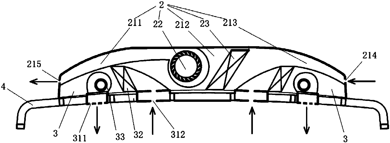
[0043] This embodiment provides a condenser air duct device, which is used in a vehicle air conditioning system, such as figure 2 As shown, the condenser air duct device 2 in this embodiment includes: a first housing, a condenser 23 and a first fan 22 . Wherein, the condenser 23 is arranged in the first casing. The first casing includes a top and a side connected to the top (the top and side of the first casing mentioned here are used in the specific use of the condenser air duct device, and the top is used as the top of the condenser air duct device (the uppermost end plate), the side is located on the side of the condenser air duct device (for connecting the top and bottom plates); wherein, the side of the first housing is provided with a first air inlet 214 and a first air outlet 215. Wherein, under the action of the first blower 22, the outside air enters the first housing through the first air inlet 214, and is discharged through the first air outlet 215 after being hea...

Embodiment 2

[0047] Preferably, this embodiment provides a condenser air duct device, compared with the previous embodiment, such as figure 2 As shown, the first fan 22 in this embodiment is installed in the first casing. Compared with the external condensing fan of the condenser air duct in the vehicle air-conditioning system of the prior art, in this embodiment, the first fan 22 is arranged in the first casing (that is, in the condenser air duct device), so that, In freezing rain or snowstorm weather, the first fan will not freeze, thereby further ensuring normal and stable operation of the vehicle air conditioning system in rainy and snowy weather.

[0048] Preferably, the first fan 22 in this embodiment and other embodiments is preferably a centrifugal fan. Compared with the axial flow fans used in the existing vehicle air-conditioning system, this embodiment uses a centrifugal fan. On the one hand, when the centrifugal fan is arranged inside the first housing, it can also ensure tha...

Embodiment 3

[0050] Preferably, this embodiment provides a condenser air duct device, compared with the above embodiments, such as figure 2 As shown, this embodiment further designs the structure of the condenser air duct device as follows: the first housing includes a first cavity 213 , a second cavity 212 and a third cavity 211 which are connected in sequence. Wherein, the first air inlet 214 is opened on the cavity wall of the first cavity 213 , and the first cavity 213 is opened on the air intake channel of the condenser air channel device. The first air outlet is located on the cavity wall of the third cavity 211, and the third cavity 211 is the air outlet air channel of the condenser air channel device; the condenser 23 and the first fan 22 are all arranged in the second cavity 22 middle. Preferably, the first blower 22 is located at a side of the second cavity 212 close to the third cavity 211 ; the condenser 213 is located at a side of the second cavity 212 close to the first cav...


PUM


Abstract

The invention relates to a condenser air channel device and a vehicle air-conditioner system. A technical scheme mainly adopted by the invention lies in that the condenser air channel device comprisesa first housing, a condenser and a first fan, wherein the first housing comprises a top and a side part connected with the top; a first air inlet and a first air outlet are formed in the side part ofthe first housing; the condenser is arranged in the first housing; and a first fan is used for enabling external air to enter the first housing from the first air inlet, and after heat exchange is performed on the external air entering the first housing by the condenser, the external air after the heat exchange is discharged outside the first housing through the first air outlet. The vehicle air-conditioner system comprises the condenser air channel device. The condenser air channel device disclosed by the invention is mainly used for guaranteeing the purpose that the vehicle air-conditionersystem can normally and stably operate in a rain and snow weather.

Description

technical field [0001] The invention relates to the technical field of air conditioning, in particular to a condenser air duct device and a vehicle air conditioning system. Background technique [0002] The vehicle air conditioning system is a device that realizes the heat exchange of the air in the cabin; it can provide passengers with a comfortable riding environment. [0003] Such as figure 1 As shown, the air-conditioning system of the existing pure electric passenger car is installed on the top of the passenger car, and the air-conditioning system mainly includes a condenser air duct and an evaporator air duct in which the housing is located. Wherein, in the condenser air duct, under the action of the condensing fan 12, the air outside the passenger car enters the condenser air duct through the air inlet 11, exchanges heat with the condenser 14, and is discharged through the air outlet 13. Wherein, the air inlet 11 and the air outlet 13 of the condenser air duct are a...

Claims


Application Information

Patent Timeline
Patent Type & Authority Applications(China)
IPC IPC(8): B60H1/00
CPCB60H1/00007B60H1/00321B60H1/00392B60H2001/00085Y02T10/88
Inventor 张有林沈军谭锋刘岩吴新龙邹建煌曹雷曹锋
Owner GREE ELECTRIC APPLIANCES INC
Why Eureka
Try Eureka