Dyed cloth dehydration full-automatic system

A fully automatic and cloth dyeing technology, applied in the field of fully automatic dyeing and dehydration systems, can solve problems such as affecting production efficiency and economic benefits, labor and time consumption, and achieve the effect of improving production efficiency and economic benefits.

Pending Publication Date: 2018-04-13
FONGS NAT ENG (SHENZHEN) CO LTD
View PDF5 Cites 2 Cited by
  • Summary
  • Abstract
  • Description
  • Claims
  • Application Information

AI Technical Summary

Problems solved by technology

It is understandable that after dehydration, it is also necessary to untie the head and tail of the dyed cloth from the central column, so the process of loading and unloading the dyed cloth into and out of the dehydrator is very laborious and time-consuming, which seriously affects production efficiency and economic benefits

Method used


Image

  • Dyed cloth dehydration full-automatic system
  • Dyed cloth dehydration full-automatic system
  • Dyed cloth dehydration full-automatic system

Examples


Embodiment Construction

[0031] In the following, in conjunction with the drawings and embodiments, a non-limiting description of the technical solutions described in the present application will be given.

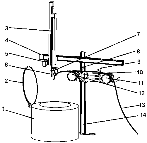
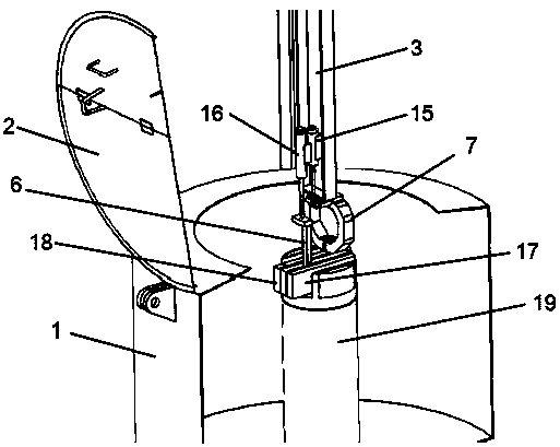
[0032] Such as figure 1 As shown, the fully automated system for dyeing fabric dehydration described in the present application includes a dehydrator 1. A cylinder head 2 is provided on the cylinder of the dehydrator 1, and the opening and closing of the cylinder head 2 is operated by the cylinder automatic device; the column of the manipulator device The axis 3, the horizontal axis 4 and the vertical axis 5 are assembled on the manipulator pillar 14 to provide synchronous movement of the XYZ axis. The rear cloth guide fork 8, the front cloth guide fork 9, the cloth lifting roller drive 10, the front cloth roller 11, and the rear cloth lifting roller 12 constitute a set of dyeing cloth transportation equipment, which is installed on the manipulator support 14. The function of the dyed cloth transport...


PUM


Abstract

The invention provides a dyed cloth dehydration full-automatic system which comprises a dehydrator, a mechanical arm device and dyed cloth transportation equipment. The mechanical arm device is arranged beside the dehydrator, a clamp for clamping cloth is arranged in the dehydrator, the clamp is arranged at the top of a center column in a dehydrator cylinder, and the mechanical arm device comprises a supporting column, a column shaft, a cross shaft and a longitudinal shaft. The supporting column of the mechanical arm device is arranged beside the dehydrator cylinder, the column shaft, the cross shaft and the longitudinal shaft can do linear motion in the three perpendicular directions, the dyed cloth transportation equipment for conveyed dyed cloth is arranged on the supporting column of amechanical arm, and the full automation of the production procedure of dyed cloth dehydration can be achieved.

Description

Technical field [0001] The application of the present invention relates to a fully automated system for dyeing cloth dehydration, which is a technical improvement of the dyeing cloth dehydration process, and belongs to the technical field of textile printing and dyeing equipment. Background technique [0002] In the dyeing industry, the operator introduces a very long piece of cloth into an overflow dyeing machine, and then connects the head and tail ends of the cloth to form an endless continuous rope loop for the dyeing machine. Cycle spray dyeing. When the spray dyeing process is completed, the dyed cloth itself is full of dye liquor, so the next process is to separate the dye liquor from the dyed cloth. The most common method is to use a rotary centrifugal dewatering machine to rotate the dyed cloth with the ends separated at high speed, and use the centrifugal force generated during the rotation to extract the excess dye liquor from the dyed cloth. This way, on the one han...

Claims


Application Information

Patent Timeline
Patent Type & Authority Applications(China)
IPC IPC(8): D06B23/04D06B23/20D06B15/10B25J9/02
CPCD06B15/10D06B23/04D06B23/20B25J9/023D06B2700/36
Inventor 徐达明
Owner FONGS NAT ENG (SHENZHEN) CO LTD
Why Eureka
Try Eureka