Bearing vibration measurement mechanism and bearing detection device

A technology for measuring vibration and bearings, which is applied in the direction of measuring devices, measuring ultrasonic/sonic/infrasonic waves, instruments, etc. It can solve the problems of affecting the measurement effect, uneven force between the inner ring and the outer ring, and automatic detection, etc., so as to improve the effect , even force, and improve the efficiency of detection

Pending Publication Date: 2018-04-13
NINGBO ZEE AUTOMATION EQUIP
View PDF0 Cites 5 Cited by
  • Summary
  • Abstract
  • Description
  • Claims
  • Application Information

AI Technical Summary

Problems solved by technology

[0004] The purpose of the present invention is to provide a bearing vibration measuring mechanism to solve the problem that the existing bearing cannot automatically detect the vibrati...

Method used


Image

  • Bearing vibration measurement mechanism and bearing detection device
  • Bearing vibration measurement mechanism and bearing detection device
  • Bearing vibration measurement mechanism and bearing detection device

Examples


Embodiment 1

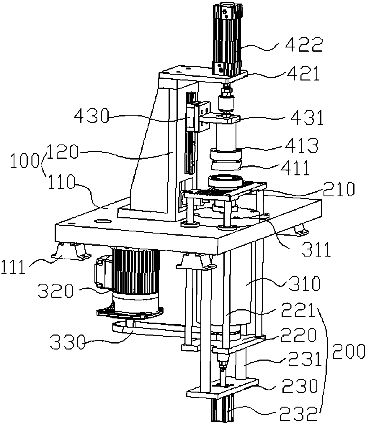
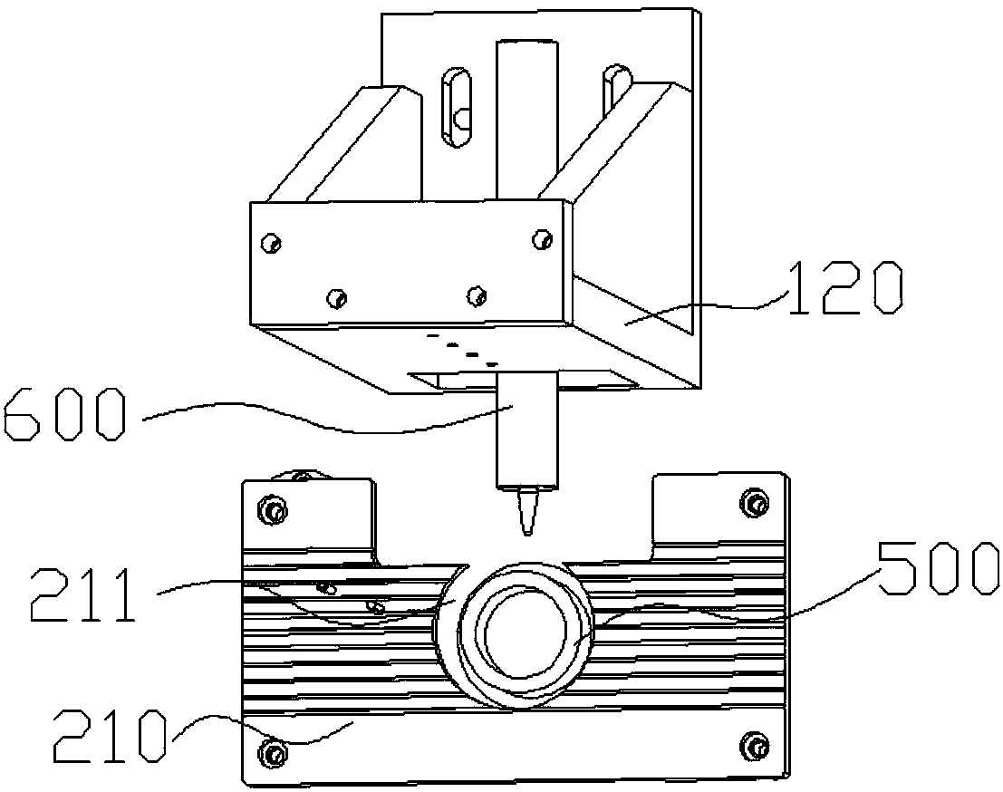
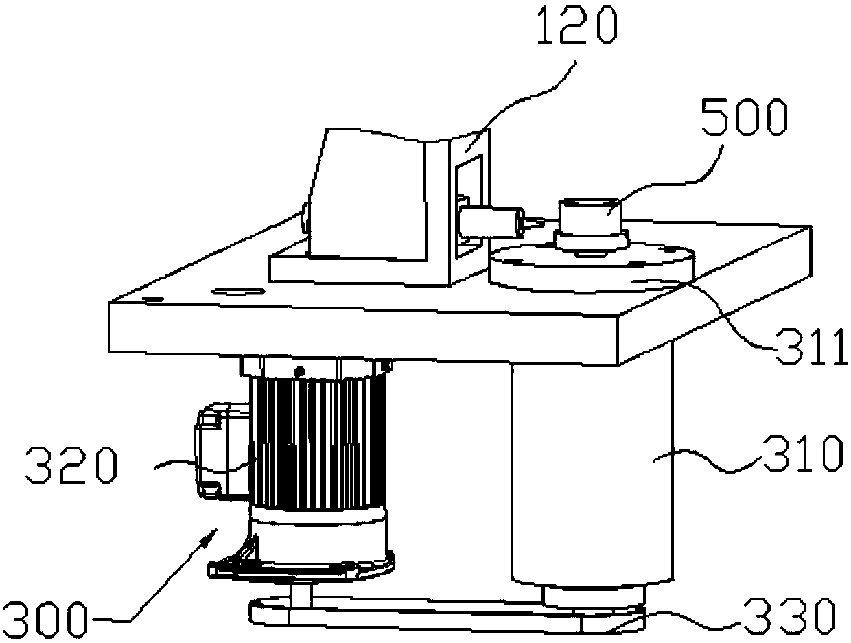
[0042] Such as figure 1 and figure 2As shown, the bearing vibration measuring mechanism provided in this embodiment includes: a support assembly 100, a backing plate assembly for bearing the bearing, a vibration measuring mandrel 500 for fixing the inner ring of the bearing, and a vibration measuring mandrel 500 for driving the bearing. The rotating rotating assembly 300, the circumferential loading assembly 400 for applying axial pressure to the outer ring of the bearing, and the vibration measuring sensor 600 for measuring the vibration of the outer ring when the inner ring of the bearing rotates; the backing plate assembly includes the backing plate 210 and The second drive assembly 200 that drives the backing plate 210 to move in the vertical direction; the backing plate 210 is arranged directly above the output end of the rotating assembly 300, and the backing plate 210 is provided with a through hole 211 that can pass through the vibration measuring mandrel 500; The lo...

Embodiment 2

[0055] The bearing detection equipment provided in this embodiment includes: a manipulator and the bearing vibration measuring mechanism provided in Embodiment 1; the manipulator can place the bearing on the backing plate 210 of the bearing vibration measuring mechanism.

[0056] In the bearing testing equipment provided in this embodiment, the bearing is placed on the backing plate 210 by the manipulator to detect the vibration value. After the test, the bearing is taken away by the manipulator to complete the automatic test and improve the efficiency of the test. Wherein, the structure and beneficial effects of the bearing vibration measuring mechanism have been described in detail above, and will not be repeated here.


PUM


Abstract

The present invention relates to the technical field of bearing detection, in particular to a bearing vibration measuring mechanism and bearing testing equipment. and a vibration sensor for measuring the vibration of the outer ring when the inner ring of the bearing rotates; the backing plate assembly includes a backing plate and a second drive assembly that drives the backing plate to move in the vertical direction; the backing plate is arranged directly above the output end of the rotating assembly , and the backing plate is provided with a through hole that can pass through the outside of the vibration measuring mandrel; the circumferential loading assembly includes a pressure head assembly and a first drive assembly for driving the pressure head assembly to move in the vertical direction; the pressure head assembly is arranged on directly above the through hole; the vibration measuring sensor is arranged at the side end of the vibration measuring mandrel. The bearing vibration measuring mechanism solves the technical problem that the existing bearing cannot be automatically detected when measuring the vibration value, and the bearing vibration measuring mechanism with a vertical structure causes uneven stress on the inner ring and the outer ring, which affects the measurement effect.

Description

technical field [0001] The invention relates to the technical field of bearing detection, in particular to a bearing vibration measuring mechanism and bearing detection equipment. Background technique [0002] Bearings are used to determine the relative movement position of the rotating shaft and other parts, and play a supporting or guiding role. The main function of the bearing is to support the rotating shaft or other moving body, guide the rotation or movement and bear the load transmitted by the shaft or parts on the shaft. In order to ensure the smooth and safe development of production activities, it is necessary to measure the quality of bearings through testing devices. Among them, in the bearing quality inspection project, the vibration value of the bearing is one of the important indicators reflecting the quality of the bearing. [0003] The existing bearing vibration measuring mechanism is usually a vertical structure. The outer ring of the bearing is pressed v...

Claims


Application Information

Patent Timeline
IPC IPC(8): G01H17/00
CPCG01H17/00
Inventor 刘建军马盈丰朱文杰潘斌
Owner NINGBO ZEE AUTOMATION EQUIP
Why Eureka
Try Eureka