
Ku-band low noise amplifier

A low-noise amplifier and amplifier technology, applied in the direction of low-noise amplifiers, amplifiers, high-frequency amplifiers, etc., can solve the problems of insufficient gain of Ku-band CMOS low-noise amplifiers, large chip area, poor anti-interference, etc., and simplify the layout area. and complexity, high single-stage gain, and the effect of reducing matching loss

Active Publication Date: 2018-04-13
BEIJING INST OF REMOTE SENSING EQUIP
View PDF9 Cites 1 Cited by
  • Summary
  • Abstract
  • Description
  • Claims
  • Application Information

AI Technical Summary

Problems solved by technology

[0003] The purpose of the present invention is to provide a Ku-band low-noise amplifier to solve the problems of insufficient gain, poor noise, poor anti-interference, and large chip area of ​​the Ku-band CMOS low-noise amplifier.

Method used


Image

  • Ku-band low noise amplifier

Examples


Embodiment Construction

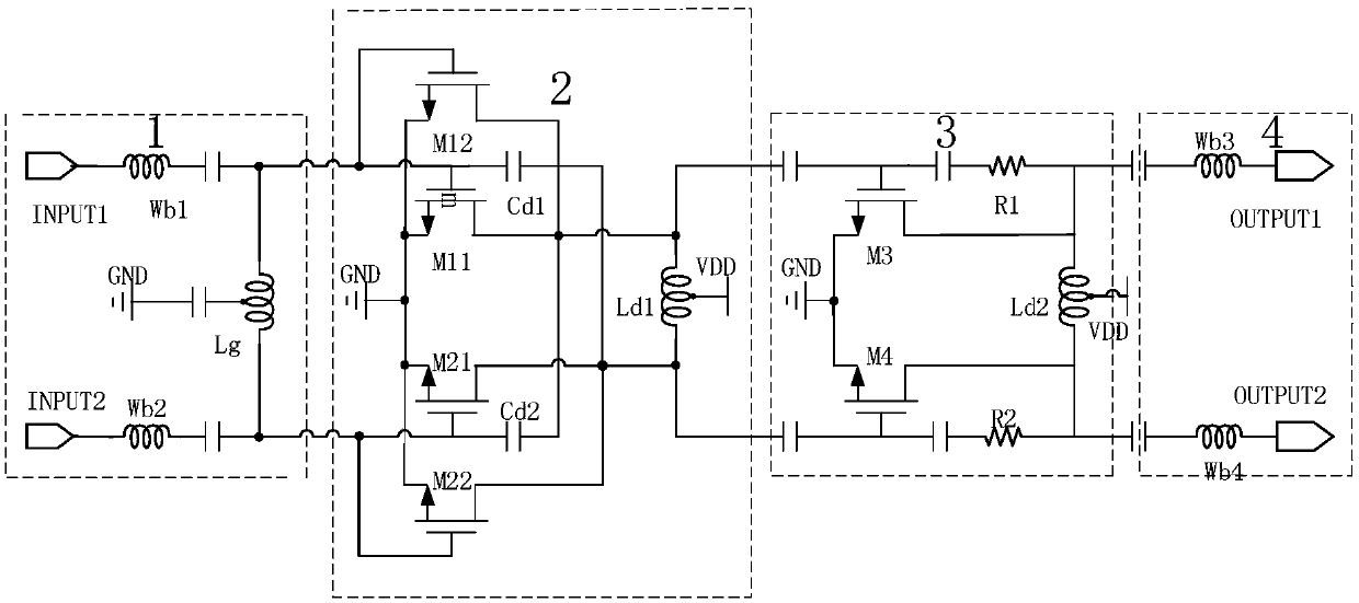
[0014] A Ku-band low-noise amplifier, comprising: a T-type input matching structure 1, a pseudo-differential amplifier 2, a common-source amplifier 3 and an output match 4, wherein the common-source amplifier 3 has RC parallel negative feedback, and the pseudo-differential amplifier 2 There is a coupling capacitance connection with the common source amplifier 3 , and there is a coupling capacitance connection between the common source amplifier 3 and the output matching 4 .

[0015] The T-type input matching structure 1 includes: a gold wire inductor Wb1, a gold wire inductor Wb2, a parallel tapped inductor Lg, and a coupling capacitor. One input terminal INPUT1 of the low noise amplifier is connected to one end of the gold wire inductor Wb1, the other input terminal INPUT2 is connected to one end of the gold wire inductor Wb2, and the other end of the gold wire inductor Wb1 is connected to one end of the parallel tapped inductor Lg and the transistor M11, transistor The gate ...


PUM


Abstract

The invention discloses a Ku-band low noise amplifier, relating to a Ku-band differential low noise amplifier circuit structure that adopts different amplification structures to perform amplificationand adopts a CMOS process. The circuit structure comprises four parts that are a first-stage pseudo-differential amplification stage, a second-stage RC parallel feedback common-source amplification circuit, and input and output matching structures using bonding wire gold wire inductors, wherein a signal enters the input matching structure from the input end, performs primary amplification throughthe first-stage pseudo-differential amplification stage, and then enters a second-stage common-source level amplifier through a coupling capacitor, and is finally sent to the output end through the output matching structure. According to the circuit structure, the problem that the Ku-band low noise amplifier that adopts the CMOS process is insufficient in amplifying ability, poor in noise performance and poor in anti-interference ability can be solved; and moreover, the matching structures and circuit layout can be simplified by adopting the input-output bonding wire gold wire inductors, and the stability and availability of the circuit can also be improved by using the differential structure.

Description

technical field [0001] The invention is an amplifier, especially a Ku-band low-noise amplifier. Background technique [0002] As the first stage of radio frequency reception, low-noise amplifiers have amplifying capability and noise performance that are critical to the performance of the entire receiving channel. At present, low-noise amplifiers using 0.18um CMOS technology are rarely used in Ku-band circuits, because even if two stages or even Three-stage and four-stage amplification, the amplification ability of the final circuit is still not high enough, the noise performance is poor, and the matching is difficult to do, and even if the single-ended structure is adopted, the number of inductors used in the circuit is still large, the chip area is large, the circuit structure is complicated, and the stability is high. , Practicality also has bigger limitation. Contents of the invention [0003] The object of the present invention is to provide a Ku-band low-noise amplif...

Claims


Application Information

Patent Timeline
IPC IPC(8): H03F1/26H03F3/19
CPCH03F1/26H03F3/19H03F2200/294H03F2200/372H03F2200/451
Inventor 聂利鹏曹玉雄刘志哲陈磊杜景超赵海明
Owner BEIJING INST OF REMOTE SENSING EQUIP
Learn More