
Stepping type precise feed bone drilling device and application thereof

A step-by-step and feeding technology, applied in the field of medical equipment, can solve the problems of drilling too deep, secondary injury, and other tissue damage, and achieve the effect of remarkable effect, simple operation and obvious effect.

Inactive Publication Date: 2018-04-17
SHANDONG UNIV
View PDF9 Cites 3 Cited by
  • Summary
  • Abstract
  • Description
  • Claims
  • Application Information

AI Technical Summary

Problems solved by technology

If there is a wrong judgment by the doctor or lack of experience, it may cause the drill bit to penetrate too deep and injure other tissues, causing secondary injuries.

Method used


Image

  • Stepping type precise feed bone drilling device and application thereof
  • Stepping type precise feed bone drilling device and application thereof

Examples


Embodiment 1

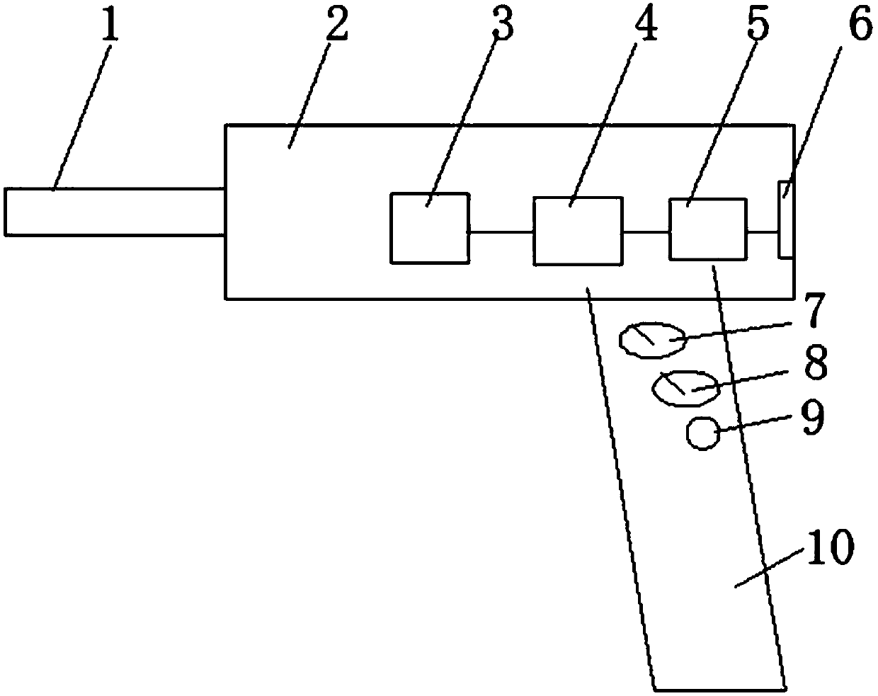
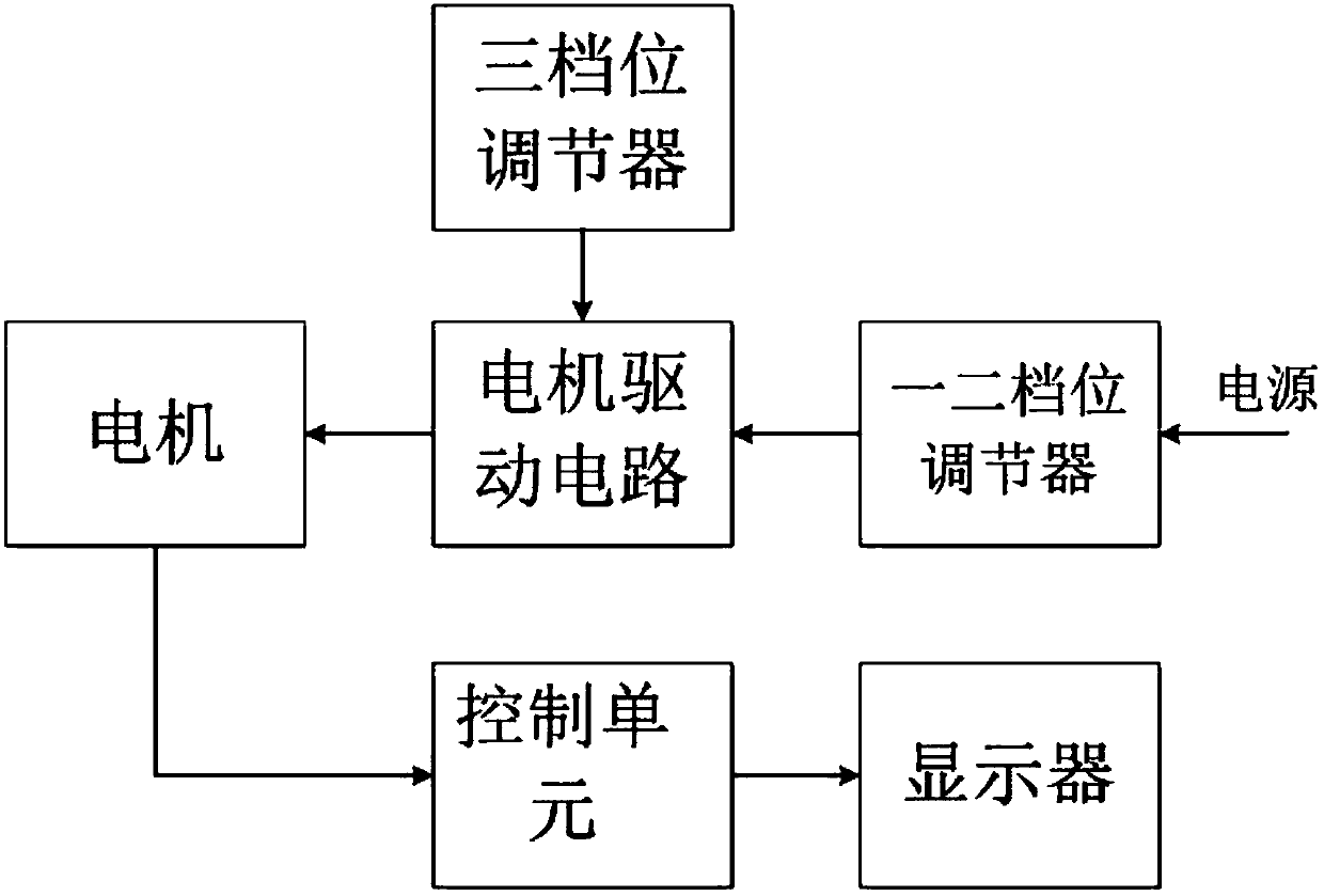
[0023] Such as figure 1 and figure 2 As shown, the present embodiment provides a step-by-step precision bone drill, which is shaped like a pistol and mainly includes an outer shell 2 and a handle 10 connected to the bottom of the outer shell. The outer shell 2 is provided with The drill bit 1, the stepper motor 3, the stepper motor drive circuit 4, the control unit 5 and the display 6 connected in sequence, wherein the front end of the drill bit 1 stretches out of the outer casing 2, and the display 6 is installed at the tail end of the outer casing 2, the operator can View some numerical information through the display screen at the rear of the outer casing; a gear adjuster is installed on the handle 10, and the gear adjuster is electrically connected with the stepper motor drive circuit 4, and the feed depth of the drill bit 1 is adjusted and controlled through the gear adjuster .

[0024] Wherein, the drill bit 1 is connected with the stepping motor 3 through a gear tran...

Embodiment 2

[0028] A kind of operation method of step-by-step precision feeding bone drill, utilizes the bone drill described in embodiment 1, and its specific operation process is as follows:

[0029] When in use, the operator holds the handle 10, drills the bone drill switch, and initially sets the bone drilling depth according to the approximate skull thickness obtained by the patient’s scan. Feed; then select different gear combinations, first use the large step gear (such as the first gear adjustment switch or the second gear adjustment switch) and then use the small step distance gear (the second gear adjustment switch or the second gear adjustment switch) Three-gear adjustment switch), by adjusting the corresponding gear multiple times to perform step feed until reaching the bone drilling depth, the drill bit 1 will perform the corresponding linear feed depth according to the selected gear, and will not cause excessive linear feed of the drill bit or too little. Using the bone dri...


PUM


Abstract

The invention relates to a stepping type precise feed bone drilling device and application thereof. The stepping type precise feed bone drilling device comprises an outer shell and a handle which is connected to the bottom of the outer shell, wherein a drill, a stepping motor, a stepping motor driving circuit, a control unit and a display which are successively connected are arranged in the outershell; the front end of the drill extends out of the outer shell; the display is arranged at the tail end of the outer shell; a gear adjuster is arranged on the handle and is electrically connected with the stepping motor driving circuit; and the feed depth of the drill is adjusted and controlled by the gear adjuster. The bone drilling device is skillful in structural design, simple to operate andconvenient to use; a traditional bone drilling mode can be replaced; and by the bone drilling device, it can be ensured that in a small-step-pitch feed state, even if a skull is pierced, large allowance exists between the drill and a meningeal, other brain tissues cannot be damaged, and the medical safety of a patient is protected to a maximum extent. Actions are obvious, effects are remarkable,and thus, the stepping type precise feed bone drilling device is worthy of being popularized and used.

Description

technical field [0001] The invention relates to a step-by-step precision bone drill and its application, belonging to the technical field of medical devices. Background technique [0002] At present, when using DBS (deep brain stimulation) surgery for Parkinson's treatment, it is necessary to open a hole in the brain. The current method is mainly to drill the head by manual feeding. When judging whether to drill through, It is always necessary for the doctor to judge according to the feedback force and feel of the drill bit after drilling. If there is a wrong judgment by the doctor or lack of experience, it may cause the drill bit to penetrate too deeply and injure other tissues, causing secondary injuries. [0003] The structure of the human brain includes hair, scalp, skull, meninges and brain tissue. The scalp plays a covering role, the skull mainly plays a protective role, and the lower part of the skull is the meninges, which are elastic. Generally, there is a gap of ...

Claims


Application Information

Patent Timeline
Patent Type & Authority Applications(China)
IPC IPC(8): A61B17/16
CPCA61B17/1604A61B17/1615A61B17/1628A61B17/1695
Inventor 周军潘春阳皇攀凌张旭涛赵峰
Owner SHANDONG UNIV
Learn More