
High-pressure cleaning machine

A technology of a high-pressure cleaner and body, applied to cleaning methods and appliances, cleaning methods using liquids, chemical instruments and methods, etc., which can solve problems such as inconvenient storage and placement, inability to separate, and the cleaning machine does not have a self-priming function , to achieve the effect of convenient and quick use, time-saving and labor-saving assembly

Pending Publication Date: 2018-04-17
CHANGZHOU GLOBE CO LTD
View PDF0 Cites 6 Cited by
  • Summary
  • Abstract
  • Description
  • Claims
  • Application Information

AI Technical Summary

Problems solved by technology

[0002] With people's demand for cleanliness, high-pressure cleaners are used more and more widely, and are widely used in cleaning dirty places such as cars, courtyards, roads, fences, etc. Currently, the cleaners on the market generally have the following defects: the cleaners do not have automatic The suction function leads to limited use and needs to be connected to an external water source with pressure input or tap water; the washing machine does not have a separate water inlet structure and needs to be connected to a nearby water source to work; the washing machine is moved and stored through a single handle or wheel structure The structure is large and takes up a lot of space; the washing machine is integral, and the water storage device (bucket) is permanently combined with the body and cannot be separated. The overall space of the washing machine is very large, which is inconvenient to store and place. Larger, when the user moves the high-pressure cleaner, it is not convenient to move, and he cannot find a good place to focus, and the movement is laborious

Method used


Image

  • High-pressure cleaning machine
  • High-pressure cleaning machine
  • High-pressure cleaning machine

Examples


Embodiment Construction

[0031] In order to make the objectives, technical solutions, and advantages of the present invention clearer, the present invention will be described in detail below with reference to the accompanying drawings and specific embodiments.

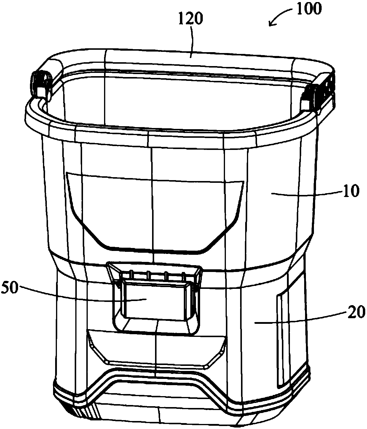
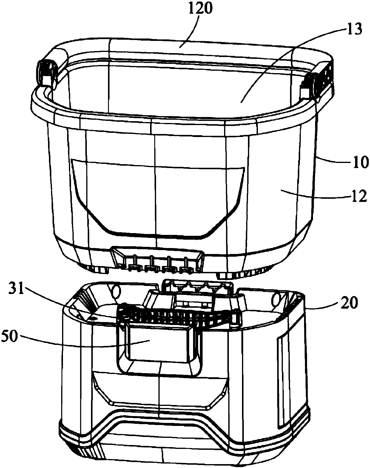
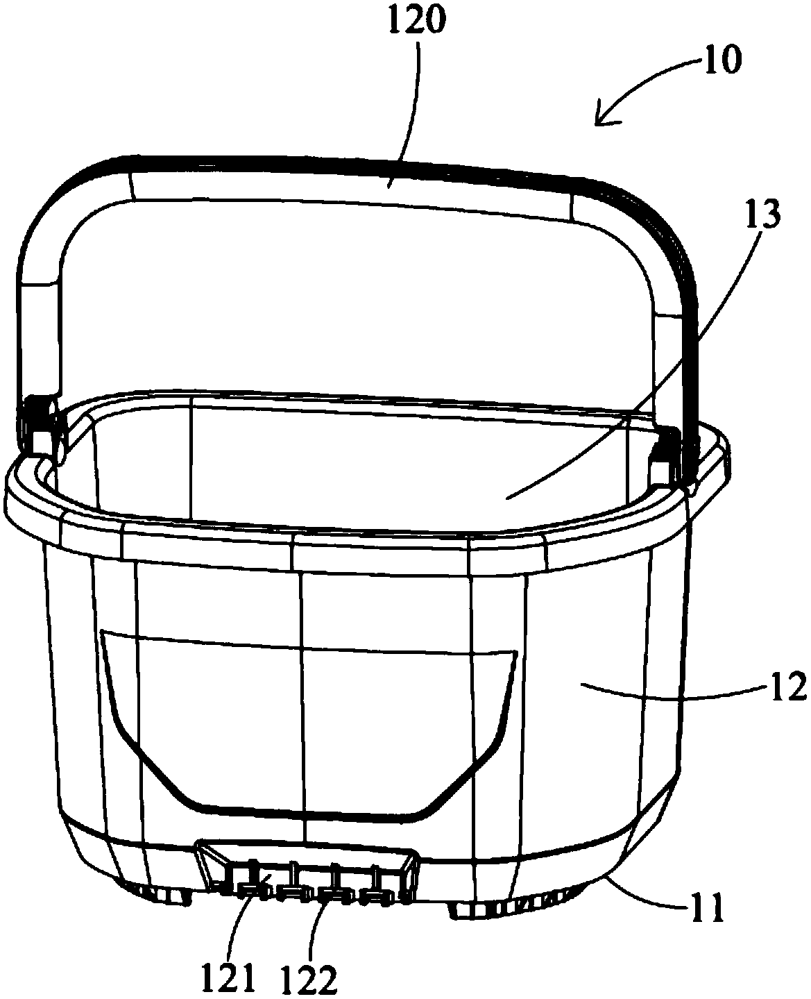
[0032] See Figure 1 to Figure 6 As shown, the present invention discloses a high-pressure washer 100, which includes a water storage device 10 and a body 20 disposed below the water storage device 10. The body 20 includes a casing 30, a water pump 40, and a power device (not shown) for driving the water pump 40 to work. (Shown) and a pair of buckle devices 50. The water pump 40 and the power device (not shown) are located in the casing 30. The buckle device 50 fixes the outside of the casing 30 for buckling the water storage device 10 on the body 20 . The power unit is a gasoline engine, a diesel engine, an induction motor, a series motor, a brush motor, a brushless motor or a DC motor.

[0033] The structure of the water storage device 10 is sim...


PUM


Abstract

Disclosed is a high-pressure cleaning machine. The high-pressure cleaning machine comprises a machine body; the machine body comprises a machine shell, a water pump and a power device which is in transmission connection with the water pump; and the water pump and the power device are located in the machine shell. The water pump comprises a pump body, a plunger cavity, a water inlet hole used for being connected with a water source, a plunger and a water outlet hole used for being discharging water out of the pump body, wherein the water inlet hole and the water outlet hole are formed in the pump body and communicate with the plunger cavity; the plunger reciprocates in the plunger cavity; a water inlet one-way valve is installed in the water inlet hole; and a water outlet one-way valve is installed in the water outlet hole. In this way, the water pump has the self-suction function, and the high-pressure cleaning machine cannot be geographically limited, can work as long as the water source exists and is convenient to use.

Description

Technical field [0001] The invention relates to a high-pressure cleaner, in particular to a high-pressure cleaner with a water pump. Background technique [0002] With people’s demand for cleanliness, the application of high-pressure cleaners has become more and more extensive, and they are widely used to clean dirty places such as cars, courtyards, roads, and fences. The current cleaning machines on the market generally have the following defects: The suction function leads to limited use. It needs to be connected to an external water source with pressure input or tap water; the washing machine does not have a separate water inlet structure, and it needs to be connected to the nearest water source to work; the washing machine is moved and stored through a single handle or wheel structure The structure is large, and the space is large; the washing machine is integral, the water storage device (bucket) is permanently integrated with the body, and cannot be separated. The overall s...

Claims


Application Information

Patent Timeline
IPC IPC(8): B08B3/02B08B13/00
CPCB08B3/024B08B3/026B08B13/00
Inventor 凌应堂
Owner CHANGZHOU GLOBE CO LTD
Learn More