
Lightweight high-rigidity gantry machining center machine base

A machining center and high rigidity technology, applied in the direction of metal processing machinery parts, metal processing equipment, manufacturing tools, etc., can solve the problems of poor casting stability, high cost, and heavy casting weight

Pending Publication Date: 2018-04-17
湖南巨人机床集团有限公司
View PDF0 Cites 1 Cited by
  • Summary
  • Abstract
  • Description
  • Claims
  • Application Information

AI Technical Summary

Problems solved by technology

In order to ensure the rigidity and strength of the base, the traditional CNC milling machine generally adopts the method of thickening, heightening, and encrypting the wall thickness of the base casting and the internal reinforcing ribs. However, due to the material characteristics of gray cast iron, casting defects are prone to occur when the wall thickness is thicker. Moreover, the internal stress will increase, the stability of the casting will deteriorate, and the weight of the casting will increase at the same time, and the cost will be higher

Method used


Image

  • Lightweight high-rigidity gantry machining center machine base
  • Lightweight high-rigidity gantry machining center machine base
  • Lightweight high-rigidity gantry machining center machine base

Examples


Embodiment Construction

[0017] The following will clearly and completely describe the technical solutions in the embodiments of the present invention with reference to the accompanying drawings in the embodiments of the present invention. Obviously, the described embodiments are only some, not all, embodiments of the present invention. Based on the embodiments of the present invention, all other embodiments obtained by persons of ordinary skill in the art without making creative efforts belong to the protection scope of the present invention.

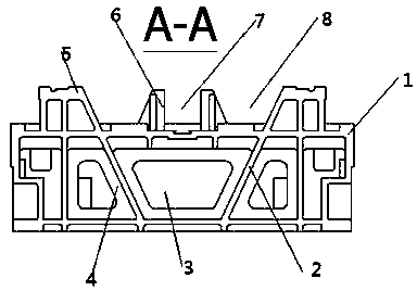
[0018] see Figure 1~3 , in an embodiment of the present invention, a light-weight and high-rigidity gantry machining center machine base includes a machine base 1, the base 1 is composed of two parallel base plates downward, and a reinforcing rib 2 is passed between the two base plates The connection is fixed, the reinforcing rib 2 is an inverted W shape, the triangular-shaped tips on both sides of the upper end of the reinforcing rib 2 pass through the base ...


PUM


Abstract

The invention discloses a lightweight high-rigidity gantry machining center machine base. The lightweight high-rigidity gantry machining center machine base comprises a machine base body. A base is composed of two downwards parallel base plates. The two base plates are connected and fixed through a strengthening rib. The strengthening rib is in an inverted-W shape. The sharp ends of the triangularshapes of the two sides of the upper end of the strengthening rib penetrate the top base plate, top sliding rails are arranged on the tops of the sharp ends of the triangular shapes of the strengthening rib, and the three end portions of the lower end of the strengthening rib are connected and fixed to the base plate on the lower side. The lower parts of double guide rails of the base are supported by the inverted-W-shaped strengthening rib, and the weight of a movable component workbench on the guide rails and machined workpieces is scattered through the strengthening rib, the supporting area and range are set from small to large, the interior of the base is supported by the multiple triangles likely, the casting stress of castings is reduced to be minimum, the residual stress of the castings is eliminated through annealing and the rest of precipitation heat treatment, and the stability during machine tool movement is greatly improved; and meanwhile, the material cost is saved, and meanwhile rigidity is improved.

Description

technical field [0001] The invention relates to the technical field of machine tool equipment, in particular to a light-weight and high-rigidity gantry machining center base. Background technique [0002] The gantry machining center refers to the machining center where the axis of the spindle is set perpendicular to the workbench. It is mainly suitable for processing large parts. The table moves back and forth), the moving column type (the table is fixed, the gantry moves), the crane type (the table is fixed, the beam moves) and there are many types of gantry machining centers with the above composite forms. The processing characteristics, capabilities, and targeted product processing uses are not exactly the same. [0003] This design belongs to the structure improvement category of machine tool parts in the machinery industry. The base is one of the main components of the main body structure of the Gantry Machining Center (CNC), and is the basis for the movement of the X,...

Claims


Application Information

Patent Timeline
Patent Type & Authority Applications(China)
IPC IPC(8): B23Q1/01
CPCB23Q1/015
Inventor 刘军李雄彭卫专
Owner 湖南巨人机床集团有限公司
Learn More