
Deep blind hole housing body rapid measurement device and measurement and compensation machining methods

A technology of measuring device and processing method, which is applied to metal processing equipment, measuring/indicating equipment, metal processing mechanical parts, etc., can solve the problems of low processing accuracy, easy to tremble, and it is difficult for the radome to meet the electrical performance requirements. high precision effect

Active Publication Date: 2018-04-17
湖北三江航天江北机械工程有限公司
View PDF6 Cites 3 Cited by
  • Summary
  • Abstract
  • Description
  • Claims
  • Application Information

AI Technical Summary

Problems solved by technology

In the process of deep cavity milling, the overhang of the tool is too long, it is easy to tremble, and the machining accuracy is low; the processing performance of the ceramic matrix composite material leads to large wear of the tool, which often makes the accuracy of the finished product unable to meet the requirements
In the radome manufacturing process, due to the complexity of the radome structure and molding process, it is difficult for the machined radome to meet the electrical performance requirements, which in turn has a great impact on the targeting accuracy and operational reliability of the missile.

Method used


Image

  • Deep blind hole housing body rapid measurement device and measurement and compensation machining methods
  • Deep blind hole housing body rapid measurement device and measurement and compensation machining methods
  • Deep blind hole housing body rapid measurement device and measurement and compensation machining methods

Examples


Embodiment Construction

[0028] The present invention will be further described in detail below in conjunction with the accompanying drawings and specific embodiments.

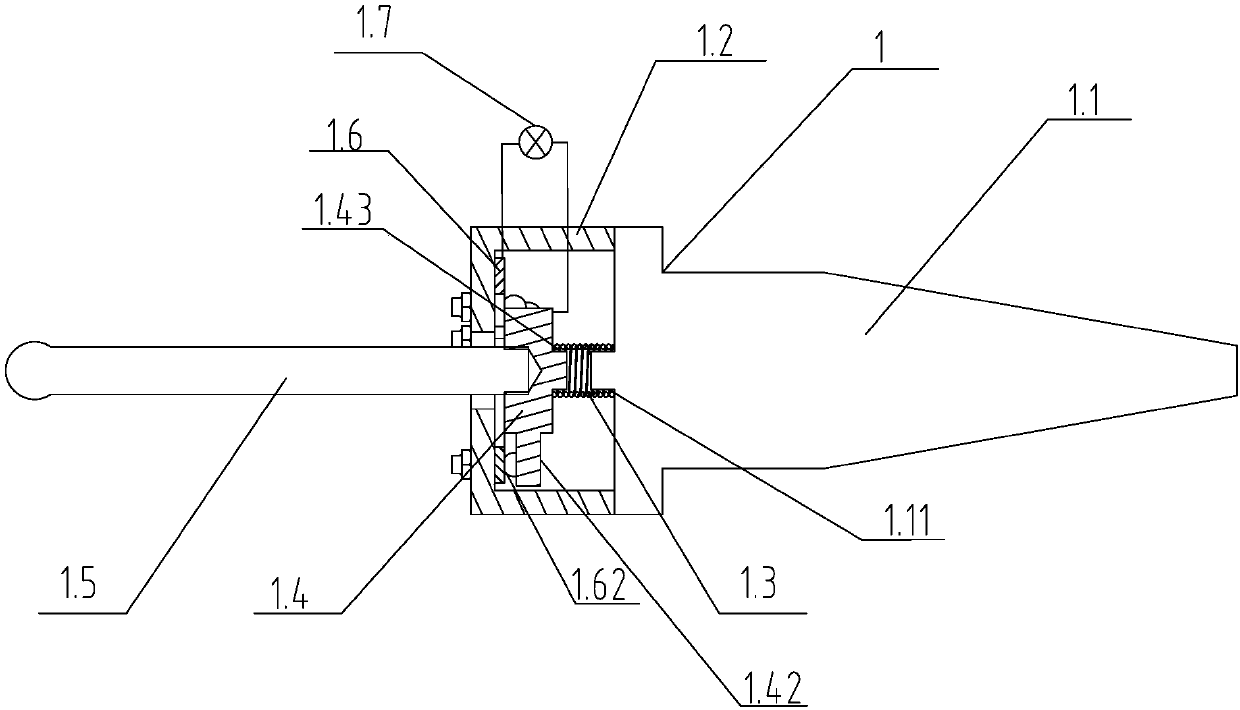
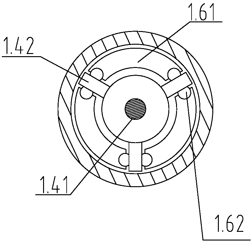
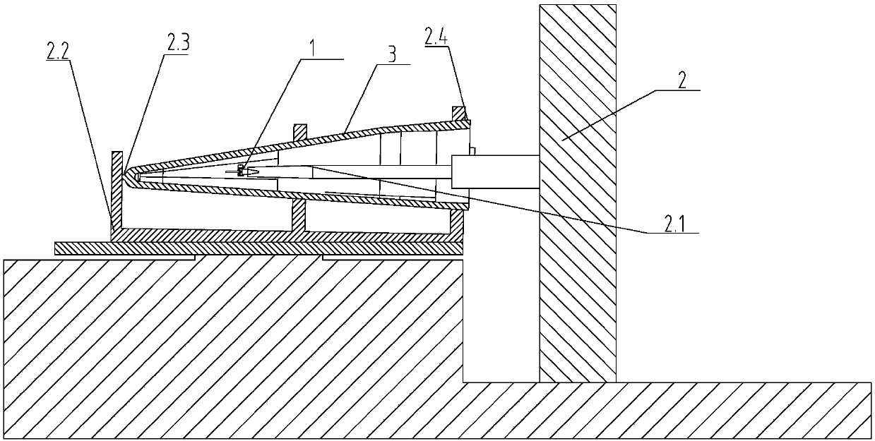
[0029] Such as figure 1 , figure 2 As shown, the deep blind hole cover rapid measuring device 1 of the present invention includes a base 1.1 coaxially arranged with the machine tool spindle 2.1, the rear end of the base 1.1 is a tapered structure, embedded in the machine tool spindle 2.1, and the front end is provided with a mounting cover 1.2, The installation cover 1.2 forms a cavity structure at the front end of the base 1.1, the front end of the inner cavity of the installation cover 1.2 is provided with a conductive plate 1.6, and the middle part of the installation cover 1.2 and the conductive plate 1.6 is provided with a through hole for the probe 1.5 to pass through. The front end of 1.5 is an arc surface, and the rear end passes through the mounting cover 1.2 and the conductive plate 1.6, and extends into the moving plate 1...


PUM


Abstract

The invention discloses a deep blind hole housing body rapid measurement device and measurement and compensation machining methods. The device comprises a base, wherein the base is arranged to be coaxial with a machine tool main shaft. The rear end of the base is embedded into the machine tool main shaft. The front end of the base is provided with a mounting cover. A cavity structure is formed bythe mounting cover at the front end of the base. An electric conduction plate is arranged at the front end of an inner cavity of the mounting cover. The middle of the mounting cover and the middle ofthe electric conduction plate are each provided with a through hole, wherein the through holes allow a probe to penetrate. The rear end of the probe penetrates the mounting cover and the electric conduction plate and extends into a moving plate, wherein the moving plate is mounted in the inner cavity of the mounting cover. The front end face of the moving plate is attached to the rear end face ofthe electric conduction plate. The rear end of the moving plate is provided with a spring. A spring locating table is arranged in the middle of the base. One end of the spring is connected with the rear end of the moving plate, and the other end of the spring is connected with the spring locating table. The electric conduction plate and the moving plate are in series connection with a diode through wires. The output end of the diode is connected with a machine tool control circuit. According to the deep blind hole housing body rapid measurement device and the measurement and compensation machining methods, rapid measurement of a housing body is achieved through a photoelectric measurement device; and the compensation machining method is achieved through post-processing of measurement data.

Description

technical field [0001] The invention relates to a high Mach special-shaped deep blind-hole radome processing technology, in particular to a deep blind-hole radome rapid measurement device and a measurement and compensation processing method. Background technique [0002] With the development of missile weapon systems in the direction of high speed, precision strike, and long endurance, various advanced tactical missiles fly at high Mach speeds. As the protective cover of the seeker antenna, the radome is an important part of the "eye in the sky" of the missile weapon system. It has multiple functions such as wave penetration, flow diversion, heat protection, and load bearing. According to the use requirements and characteristics of the radome, the internal and external structures are all shaped curved surfaces, and the depth of the inner cavity reaches 1311mm. Due to the large measurement range of the profile and the high precision of the wall thickness measurement, there is...

Claims


Application Information

Patent Timeline
IPC IPC(8): B23Q17/20B23Q23/00
CPCB23Q17/20B23Q23/00
Inventor 卓艾宝张志斌吴钦周荣军
Owner 湖北三江航天江北机械工程有限公司
Learn More