Rotatable and multifunctional road maintenance equipment

A road maintenance and multi-functional technology, applied in the field of indexable multi-functional road maintenance equipment, can solve problems such as hidden dangers, excessive dust, power optimization, etc., and achieve the effect of safe construction process, high degree of intelligence, and high degree of integration

Active Publication Date: 2018-04-17
BAOJI UNIV OF ARTS & SCI
View PDF6 Cites 1 Cited by
  • Summary
  • Abstract
  • Description
  • Claims
  • Application Information

AI Technical Summary

Problems solved by technology

[0003] (1) It is necessary to use special lifting equipment to lift cutting, milling and planing equipment. These maintenance equipment are often of high quality, so there are potential safety hazards in the lifting process
[0004] (2) The degree of automation of maintenance equipment is low
The construction process requires maintenance workers to operate directly. During the construction process, there is a lot of vibration, and there is a lot of dust in the cutting and crushing process, which will cause great damage to the workers.
[0005] (3) The degree of power optimization between devices is low
The cutting machines, milling machines and other maintenance equipment equipped with road maintenance vehicles are powered by independent diesel engines, and the power is not optimized, resulting in a serious waste of resources

Method used


Image

  • Rotatable and multifunctional road maintenance equipment
  • Rotatable and multifunctional road maintenance equipment
  • Rotatable and multifunctional road maintenance equipment

Examples


Embodiment Construction

[0026] The specific content of the present invention will be described in further detail below in conjunction with the accompanying drawings and embodiments.

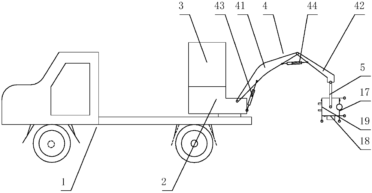
[0027] figure 1 It is a schematic diagram of the structure of the maintenance equipment of the present invention installed on the road maintenance vehicle. In the figure, the balance turntable 2 is installed on the chassis 1 of the maintenance vehicle, which is a commonly used rotary platform structure. The control system 3 is installed on the top of the balance turntable 2 to realize the automatic control of the entire machine tool. The articulated mechanical arm 4 is articulated at the side of the balance turntable 2. The articulated robot arm 4 of this embodiment includes a first arm 41 and a second arm 42. The first arm 41 is connected to the balance turntable 2 through a first hydraulic cylinder 43. A hydraulic cylinder 43 controls the amplitude of the first arm 41, the second arm 42 is connected with the first ar...


PUM


Abstract

The invention relates to rotatable and multifunctional road maintenance equipment. The rotatable and multifunctional road maintenance equipment comprises a balance rotary table and a control system, wherein an equipment centralized platform is connected onto the balance rotary table through a joint robot arm and comprises a fixed platform and a rotary platform, the fixed platform and the rotary platform are connected through a position screw-nut mechanism which is connected with a position change gear set through a gear-worm assembly, the position change gear set is connected with a position shifting clutch which is connected with a drive gear set mounted on an output shaft of a hydraulic motor, and the drive gear set is connected with a cutting assembly and a milling-planing assembly anddrives the cutting assembly and the milling-planing assembly to work. Various functions such as milling-planing, cutting, crack pouring and the like are integrated, power is supplied to the milling-planing assembly and the cutting assembly by one power source, and the rotatable and multifunctional road maintenance equipment is high in automation degree, more convenient to operate and applicable torepair of early damage of a road and can accurately position small cracks and small potholes in the road precisely and maintain the road automatically.

Description

technical field [0001] The invention belongs to the field of asphalt pavement maintenance, and in particular relates to an indexable multifunctional road maintenance machine tool. Background technique [0002] After the roads that have been built have been used for a period of time, diseases such as road surface cracks and small potholes often appear. If these diseases are not repaired in time, they will evolve into larger diseases, which will increase the cost and difficulty of maintenance. At present, road maintenance vehicles are equipped with joint filling machines on the maintenance vehicles to deal with cracks, and equipped with milling machines and cutting machines to deal with potholes. However, configuring these devices independently has the following problems: [0003] (1) It is necessary to use special lifting equipment to lift cutting, milling and planing equipment. These maintenance equipment are often of high quality, so there are potential safety hazards in t...

Claims


Application Information

Patent Timeline
IPC IPC(8): E01C23/06E01C23/088E01C23/09
CPCE01C23/06E01C23/088E01C23/092
Inventor 张卫亮李亮李飞舟魏宏波任思源王玮王鑫高红卫
Owner BAOJI UNIV OF ARTS & SCI
Why Eureka
Try Eureka