Flow swirling and flow intercepting device

A shut-off device and swirl valve technology, applied in water supply devices, waterway systems, drainage structures, etc., can solve problems such as high operating costs, environmental hazards, and difficult dredging work, improve installation stability, and reduce downstream water seepage. , the effect of reducing the impact force

Pending Publication Date: 2018-04-17
MIN OF WATER RESOURCES HANGZHOU MACHINERY DESIGN INST
View PDF5 Cites 0 Cited by
  • Summary
  • Abstract
  • Description
  • Claims
  • Application Information

AI Technical Summary

Problems solved by technology

Due to the existence of silt, in the absence of a large external force, the drainage capacity of the drainage pipe is low, and there will be water seepage, water leakage and overflow of the collection well
At the same time, during heavy rainfall, it is not conducive to the orderly discharge of rainwater
[0003] Although in recent years, a series of relatively mature dredging technologies and dredging equipment have been developed and widely used, but there is still a lack of economical and applicable dredging technologies and dredging equipment, and its dredging work is still a problem
Moreover, the equipment required for dredging of drainage pipes is expensive, the operation cost is high, and in some cases, the dredging work is dangerous, and it also causes harm to the surrounding environment

Method used


Image

  • Flow swirling and flow intercepting device
  • Flow swirling and flow intercepting device
  • Flow swirling and flow intercepting device

Examples


Embodiment 1

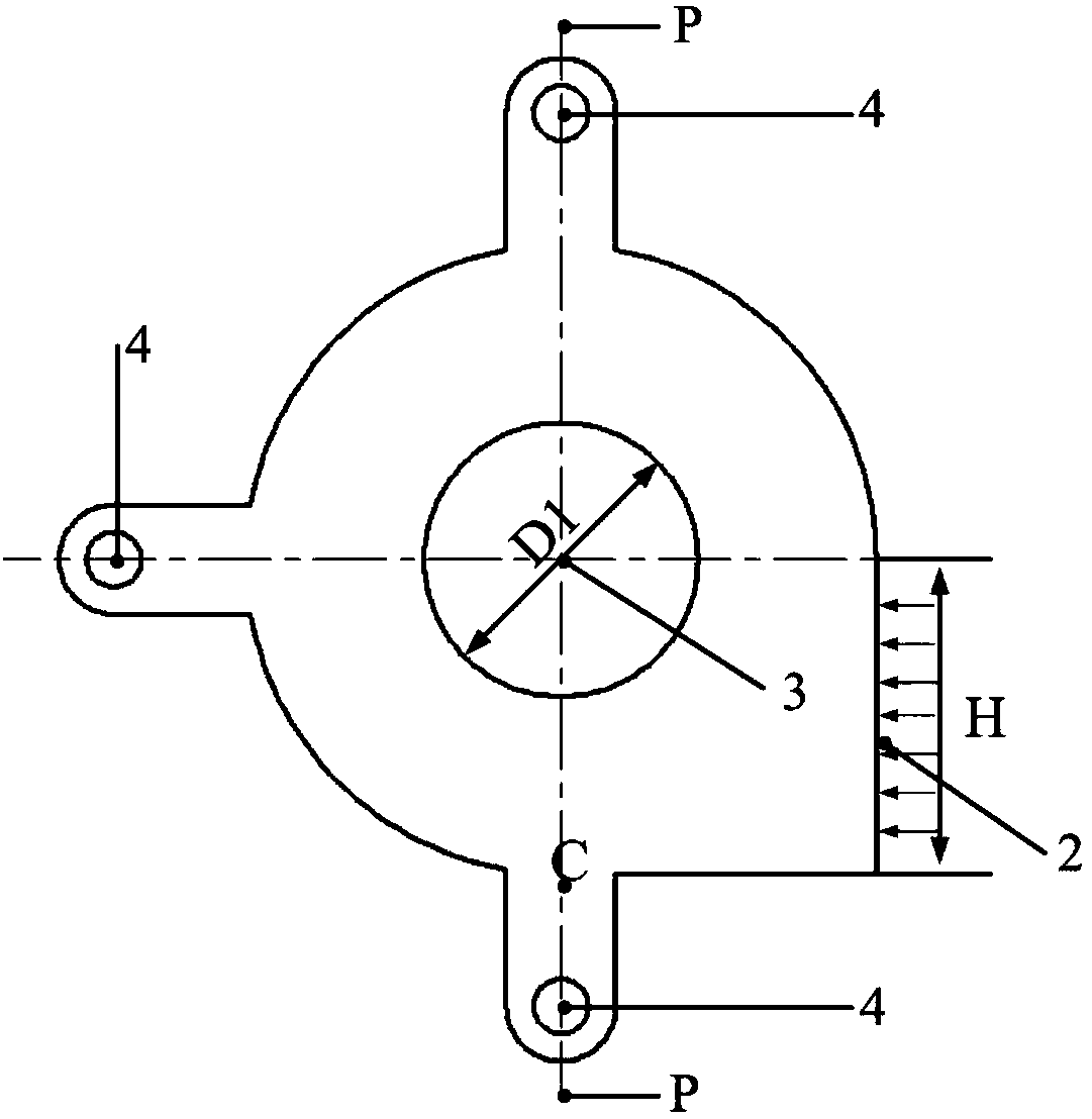
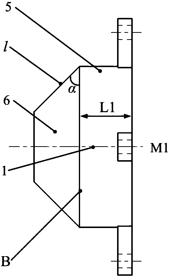
[0050] The swirl flow interceptor provided according to the present invention comprises an inlet 2 and an outlet 3, and the outlet 3 is located on the center line of the cylindrical outer shell of the swirl flow interceptor 1 . The inlet section is rectangular, area A1=34500mm 2 , the outlet section is circular, area A2 = 31400mm 2 .

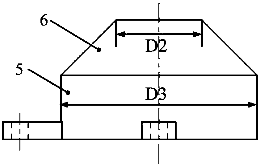
[0051] The cylindrical outer shell 5 is not a complete cylindrical structure, wherein the cylindrical structure only occupies 3 / 4 of the outer shell, and the remaining 1 / 4 is the inlet 2 of the rectangular section, and the width of the rectangular section is 5 of the cylindrical outer shell 5 The width is L1, the height is H, H is less than or equal to the diameter D3 of the cylindrical shell, and the rectangular cross-sectional area is greater than or equal to the cross-sectional area of ​​the outlet 3 .

[0052] By comparing the flow at the outlet of the interception well pipeline with the installation of the device of the present invention ...


PUM


Abstract

The invention discloses a flow swirling and flow intercepting device. The device comprises a flow swirling valve and a water collecting well. The flow swirling valve is fixedly installed in the watercollecting well, an inlet and an outlet are formed in the water collecting well, an inlet and an outlet are formed in the flow swirling valve, and the outlet of the flow swirling valve is communicatedwith the outlet of the water collecting well; the flow swirling valve is mainly formed by a cylindrical shell body connecting with a truncated cone-shaped shell body, the cylindrical shell body is composed of three fan-shaped cylinders and a square cylinder, and a through slot is formed in the outer surface of the square cylinder as a valve inlet; the water collecting well is of a rectangular structure, the inlet and the outlet are respectively formed in the two symmetrical side walls, the central axes of the inlet and the outlet are overlapped, and the central axis of the outlet of the flowswirling valve is overlapped with the central axes of the inlet and the outlet of the water collecting well. According to the device, an air intercepting cylinder can be formed in the center of the flow swirling and flow intercepting device, the diameter size of the air intercepting cylinder is controlled by water levels, stability of installation of the device is improved, flow intercepting effect is achieved, phenomenons of water seepage, water leakage and water overflow in down stream due to water level difference are reduced, deposit and blocking are slowed down, and flow capacity of a pipe is improved.

Description

technical field [0001] The invention relates to a flow cut-off control device, in particular to a swirl flow cut-off device. Background technique [0002] Water is the source of life and an important cornerstone of national economic development. The rational development and utilization of water resources and the protection of the water environment are important guarantees for the sustainable development of the country. Once the supply and demand of water resources are out of balance or the water environment is seriously polluted, it will lead to social and economic problems. Development lags. In recent years, with the rapid expansion of the number of cities, city scale and urban population, the discharge of urban sewage is increasing day by day, and the discharge of domestic sewage exceeds the discharge of industrial sewage. In order to realize the rapid discharge of sewage, in recent years, my country has successively built and put into operation a number of large-scale se...

Claims


Application Information

Patent Timeline
Patent Type & Authority Applications(China)
IPC IPC(8): E03F5/10
CPCE03F5/106
Inventor 马光飞吴燕明方勇程文韬李桃李超章蕾郑寓
Owner MIN OF WATER RESOURCES HANGZHOU MACHINERY DESIGN INST
Why Eureka
Try Eureka