Variable-frequency magnetoresistive effect element and oscillator, detector, and filter using the same

一种磁电阻、效应的技术,应用在功率振荡器、磁场控制的电阻器、电气元件等方向,能够解决占有面积增加、元件工作能量增加等问题

Active Publication Date: 2018-04-17
TDK CORPARATION
View PDF7 Cites 6 Cited by
  • Summary
  • Abstract
  • Description
  • Claims
  • Application Information

AI Technical Summary

Problems solved by technology

As a result, the problem of causing a substantial increase in the operating energy of the element
In addition, since it is necessary to install an electromagnet near the oscillating element, the overall occupied area tends to increase significantly.

Method used


Image

  • Variable-frequency magnetoresistive effect element and oscillator, detector, and filter using the same
  • Variable-frequency magnetoresistive effect element and oscillator, detector, and filter using the same
  • Variable-frequency magnetoresistive effect element and oscillator, detector, and filter using the same

Examples


no. 1 approach

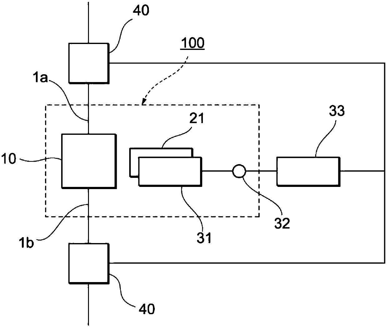
[0090] figure 1 It is a schematic diagram showing the configuration of the frequency variable magnetoresistance effect element 100 according to the first embodiment of the present invention. The frequency variable magnetoresistance effect element 100 includes a magnetoresistance effect element 10 , a magnetic field applying mechanism 21 , an electric field applying mechanism 31 and a control terminal 32 . The input signal line 1 a and the output signal line 1 b are connected to the magnetoresistance effect element 10 . The input signal line 1a and the output signal line 1b are respectively used for transmitting input signals and output signals. The control terminal 32 is connected to the electric field applying mechanism 31 , and by applying positive or negative voltage from the control terminal 32 , an electric field having a predetermined magnitude and direction can be applied to the magnetoresistance effect element via the electric field applying mechanism 31 . In this em...

no. 2 approach

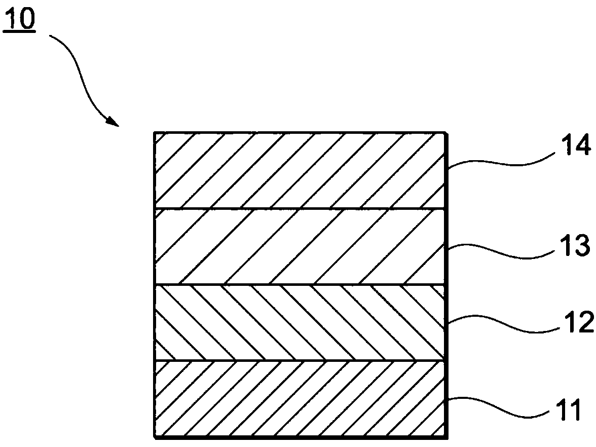
[0133] Figure 4 It is a schematic diagram showing the positional relationship among the magnetoresistance effect element 10 , the magnetic field applying mechanism 21 and the electric field applying mechanism 31 according to the second embodiment of the present invention. The magnetoresistance effect element 10 includes a control layer 11 , a magnetization free layer 12 with a variable magnetization direction, an intermediate layer 13 and a magnetization fixed layer 14 with a constant magnetization direction. The magnetization fixed layer 14 is made of a ferromagnetic material, and its magnetization direction is actually fixed to one direction in the plane of the magnetization fixed layer. The magnetic field applying mechanism 21 has a function of applying a magnetic field to the control layer 11 in a direction perpendicular to the stacking direction. The electric field applying mechanism 31 has a function of applying an electric field to the control layer 11 in a direction ...

no. 3 approach

[0138] Figure 5 It is a schematic diagram showing the positional relationship among the magnetoresistance effect element 10 , the magnetic field applying mechanism 21 and the electric field applying mechanism 31 according to the third embodiment of the present invention. The magnetoresistance effect element 10 includes a control layer 11 , a magnetization free layer 12 with a variable magnetization direction, an intermediate layer 13 and a magnetization fixed layer 14 with a constant magnetization direction. The magnetization fixed layer 14 is made of a ferromagnetic material, and its magnetization direction is actually fixed to one direction in the plane of the magnetization fixed layer. The magnetic field applying mechanism 21 has a function of applying a magnetic field to the control layer 11 in a direction perpendicular to the plane. The electric field applying mechanism 31 has a function of applying an electric field to the control layer 11 in a direction perpendicular ...


PUM


Abstract

The invention aims to provide a variable-frequency magnetoresistive effect element stable in frequency feature and substantially reduced in working energy and a device employing the same. The variable-frequency magnetoresistive effect element includes a magnetoresistive effect element, a magnetic-field applying mechanism that applies a magnetic field to the magnetoresistive effect element, an electric-field applying mechanism that applies an electric field to the magnetoresistive effect element, and a control terminal connected to the electric-field applying mechanism and used for applying a voltage that varies in at least one of magnitude and polarity to the electric-field applying mechanism. The magnetoresistive effect element contains an antiferromagnetic material or ferrimagnetic material having a magnetoelectric effect. A spin torque oscillation frequency or spin torque resonance frequency of the magnetoresistive effect element is controlled by varying the voltage applied via thecontrol terminal in at least one of magnitude and polarity.

Description

technical field [0001] The invention relates to a frequency-variable magneto-resistance effect element utilizing magneto-resistance effect. The frequency-variable magneto-resistance effect element can be applied to oscillators, wave detectors, filters and the like required for wireless communication. Background technique [0002] In recent years, as mobile terminals such as smartphones have become smaller and more functional, the number and possible occupied area of ​​electronic components used in the terminals have tended to decrease. On the other hand, due to the increase in communication speed and the diversification of applications, etc., the frequency and the number of frequency bands used tend to increase. In order to meet these requirements, a high-frequency component corresponding to multiple frequency bands capable of controlling multiple frequency bands with a single component is required. [0003] Oscillating (or resonant) elements that utilize the magnetoresista...

Claims


Application Information

Patent Timeline
Patent Type & Authority Applications(China)
IPC IPC(8): H01L43/08H03B15/00
CPCH03B15/006H10N50/10G01R33/093G01R33/098H03H2/00H03H2/001H01F10/3286H01F10/329G01R33/09H01F10/002H01F10/3218H10N50/80H10N50/85H01F1/147H03H11/04
Inventor 柴田龙雄
Owner TDK CORPARATION
Why Eureka
Try Eureka