Check patentability & draft patents in minutes with Patsnap Eureka AI!

Over-temperature protection circuit

An over-temperature protection circuit and detection circuit technology, applied in emergency protection circuit devices, circuit devices, emergency protection devices with automatic disconnection, etc., can solve the problems of overheating and burning out of semiconductor components

Inactive Publication Date: 2018-04-17
深圳市凌康技术有限公司
View PDF4 Cites 6 Cited by
  • Summary
  • Abstract
  • Description
  • Claims
  • Application Information

AI Technical Summary

Problems solved by technology

Obviously, such hysteresis will cause some high temperature semiconductor components to overheat and burn out

Method used


Image

  • Over-temperature protection circuit
  • Over-temperature protection circuit
  • Over-temperature protection circuit

Examples


Embodiment Construction

[0010] The present invention will be described in detail below in conjunction with the accompanying drawings and embodiments.

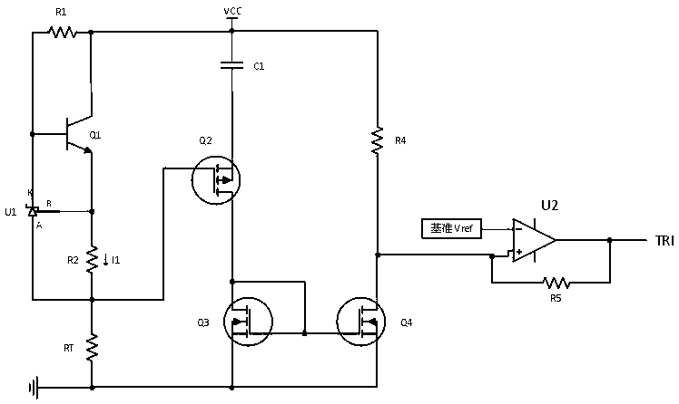
[0011] The over-temperature protection circuit provided by the embodiment of the present invention is as attached figure 1 As shown, it includes a detection circuit that detects the rate of temperature rise and an output circuit that shuts off the signal. The detection circuit monitors the temperature rise, and once the temperature is too high, the output circuit cuts off the current signal.

[0012] As shown in the figure, the detection circuit includes a reference current source U1, a first transistor Q1, a P-channel MOS transistor Q2, a first N-channel MOS transistor Q3, a second N-channel MOS transistor Q4, a capacitor C1, and a first resistor R1, the second resistor R2 and the adjustable resistor RT; the positive terminal of the reference current source U1 is connected to the b terminal of the P-channel MOS transistor Q2, and its negative termina...


PUM


Abstract

The invention provides an over-temperature protection circuit comprising a detection circuit for detecting a temperature rising rate and an output circuit for signal shutdown. The detection circuit monitors a temperature rise condition and outputs a circuit current disconnection signal once the temperature is too high. The detection circuit includes a reference current source, a first triode, a Pchannel MOS tube, a first N channel MOS tube, a second N channel MOS tube, a capacitor, a first resistor, a second resistor, and an adjustable resistor. The output circuit consists of a reference voltage source and a comparator. According to the invention, the detection circuit for detecting a temperature rising rate and the output circuit for signal shutdown form the over-temperature protection circuit and the over-temperature protection circuit is capable of monitoring the temperature rising rate, so that over-temperature protection in the circuit is realized.

Description

technical field [0001] The invention relates to the field of protection circuits, in particular to an over-temperature protection circuit. Background technique [0002] In some high-power power modules, over-temperature protection is very important. Most of the current over-temperature protection schemes are that when the temperature exceeds a certain threshold, the over-temperature protection circuit outputs a shutdown signal, so that the chip partially or completely stops working. However, in order to detect the accuracy of the temperature, this circuit performs filtering and delay processing on the sampling signal. When the detected temperature rises rapidly and the measured temperature exceeds its threshold by a large amount, the over-temperature protection circuit starts to act. Obviously such hysteresis will cause some semiconductor components with higher temperature to overheat and burn out. Aiming at the limitations of the above circuits, this patent proposes an o...

Claims


Application Information

Patent Timeline
IPC IPC(8): H02H5/04
CPCH02H5/042
Inventor 吴永钊毕福春
Owner 深圳市凌康技术有限公司
Features
  • R&D
  • Intellectual Property
  • Life Sciences
  • Materials
  • Tech Scout
  • Unparalleled Data Quality
  • Higher Quality Content
  • 60% Fewer Hallucinations
Learn More