
Rotor manufacturing method

A manufacturing method and rotor technology, which are used in the manufacture of motor generators, stator/rotor bodies, magnetic circuit rotating parts, etc., can solve the problems of excess and reduced yield, and achieve easy control and reduce residual solidified products. The effect of reducing the amount of residual solidified material, that is, the amount of residual material

Inactive Publication Date: 2018-04-17
HONDA MOTOR CO LTD
View PDF5 Cites 4 Cited by
  • Summary
  • Abstract
  • Description
  • Claims
  • Application Information

AI Technical Summary

Problems solved by technology

[0012] However, when the resin 5a is injected by the above-mentioned transfer molding, there is a problem that a residual cured product of the resin 5a having a shape substantially the same as that of the gate 3a remains in the gate 3a of the gate mold 3 That is, excess resin known as residue, which reduces yield

Method used


Image

  • Rotor manufacturing method
  • Rotor manufacturing method
  • Rotor manufacturing method

Examples


Embodiment Construction

[0062] Hereinafter, one embodiment of the rotor manufacturing method of the present invention will be described based on the drawings. It should be noted that the drawings are viewed along the direction of the symbols.

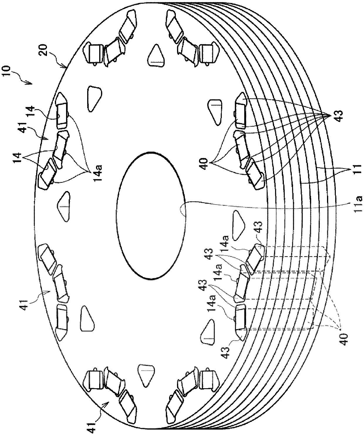
[0063] First, refer to figure 1 , the rotor core of one embodiment used in the rotor manufacturing method of the present invention will be described. A so-called embedded permanent magnet rotor 10 used in a rotating electric machine generally includes a rotor core 20 , a plurality of permanent magnets 40 , and a resin portion 43 for fixing the permanent magnets 40 to the rotor core 20 .

[0064] The rotor core 20 is formed by laminating a plurality of substantially annular electromagnetic steel sheets 11, has a shaft hole 11a in its center, and has a plurality of magnet insertion holes 14 in its outer periphery. exist figure 1 In the example shown, three magnet insertion holes 14 constitute one magnetic pole portion 41 .

[0065] A resin groove 14 a exte...


PUM


Abstract

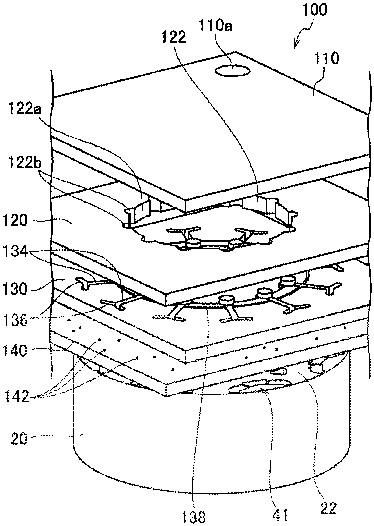
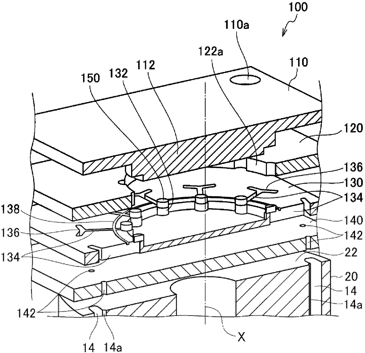
The invention provides a rotor manufacturing method capable of reducing the amount of cull which is a residual cured product of resin. In the rotor manufacturing method, a plurality of resin tablets (150) are disposed to be annularly spaced from each other in resin tablet disposing step (S230), and resin (150a) is filled between a magnet insertion hole (14) and a permanent magnet (40) in resin filling step (S240) when the plurality of resin tablets (150) are pressed by one plunger (112). Therefore, it is possible to reduce the amount of cull which is a residual cured product of a resin material.

Description

technical field [0001] The present invention relates to a rotor manufacturing method in which a rotor is manufactured by fixing magnets in a rotor core. Background technique [0002] Conventionally, in a rotating electric machine used in a hybrid vehicle or the like, a rotor is rotatably supported inside a casing. The rotor has permanent magnets fixed to a plurality of magnet insertion holes formed along the circumferential direction of the rotor core. [0003] As one of the manufacturing methods of the rotor of such a rotating electrical machine, there is known a so-called resin injection method: after inserting a permanent magnet into a magnet insertion hole of a rotor core, resin is injected from a resin injection hole provided in the magnet insertion hole, And the resin is cured to fix the permanent magnet (for example, Patent Document 1). [0004] As a method of injecting resin from the resin injection hole provided in the magnet insertion hole, there is so-called tra...

Claims


Application Information

Patent Timeline
Patent Type & Authority Applications(China)
IPC IPC(8): H02K15/03
CPCH02K15/03H02K1/2766H02K15/12H02K1/276H02K1/28
Inventor 岩本晃和梓泽庆介
Owner HONDA MOTOR CO LTD
Learn More