Pipe bending device and use method for same

A technology of pipe bending device and pipe material, which is applied in the direction of feeding device, positioning device, storage device, etc., can solve the problem of excessive waste of pipe material, and achieve the effect of simple and convenient installation work, reducing production cost and increasing continuity.

Active Publication Date: 2019-05-21
ANHUI DEXI DHI TECH
View PDF8 Cites 1 Cited by
  • Summary
  • Abstract
  • Description
  • Claims
  • Application Information

AI Technical Summary

Problems solved by technology

[0008] Aiming at the problems existing in the prior art that the remaining material of the pipe is too long due to the clamping of the pipe inside the feeding device, the waste of the remaining material is too much, the installation of the pipe is time-consuming and laborious, and it is difficult to bend in the direction of the X-axis and the Z-axis at the same time, the present invention Provided is a pipe bending device; by fixing both ends of the pipe, it can solve the problem of excessive waste of pipe material, the installation work is simple and convenient, and it is beneficial to improve work efficiency; moreover, the pipe bending device used in it can simultaneously Bending is carried out in the X-axis and Z-axis directions; in addition, the invention also discloses a method of using the device, which has the advantages of simple operation and high reliability

Method used


Image

  • Pipe bending device and use method for same
  • Pipe bending device and use method for same
  • Pipe bending device and use method for same

Examples


Embodiment 1

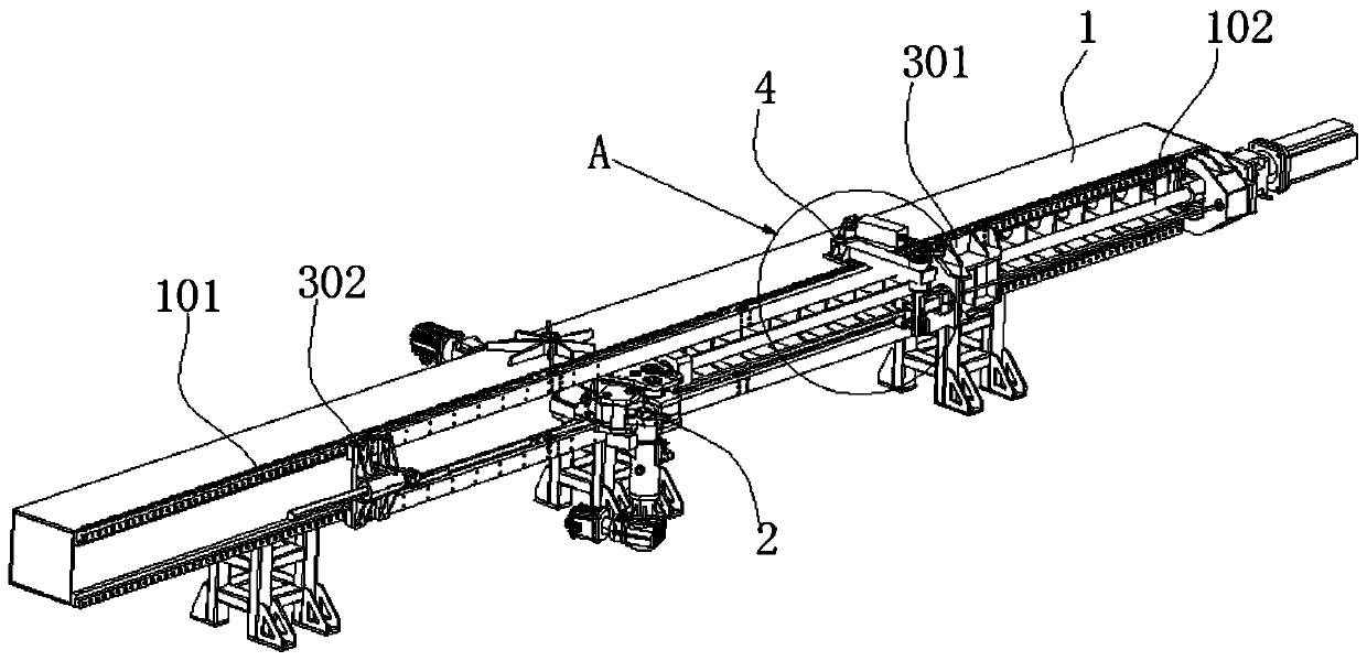
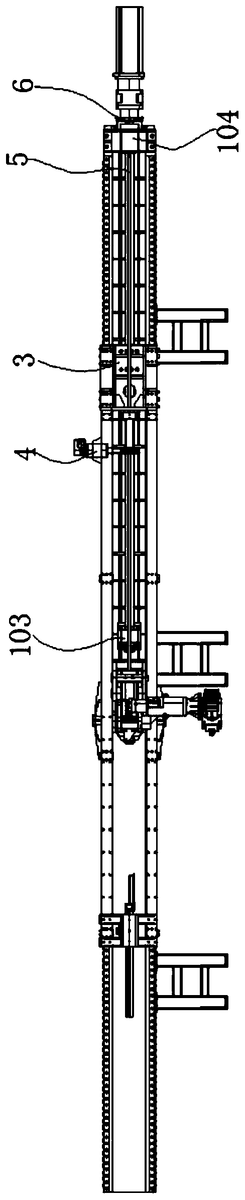
[0054] Such as figure 1 and image 3 As shown, a three-dimensional curvature pipe bending machine includes a frame 1, and the frame 1 is used as a supporting platform, and a pipe bending device 2 and a feeding device 3 are connected to one side of the frame, and the feeding device 3 includes a synchronously moving pushing mechanism 301 and a top The material mechanism 302, the pipe bending device 2 is located between the material pushing mechanism 301 and the material pushing mechanism 302, the material pushing mechanism 301 is used to push the pipe to move, and the material pushing mechanism 302 is used to tighten the pipe until the end of the pipe is in contact with the material pushing mechanism 301 are in close contact with each other, and the function of the ejector mechanism 302 can also be realized in other ways, such as using manual hand pushing. The design of the ejector mechanism 302 improves the automation productivity, saves manpower, and is also conducive to the s...

Embodiment 2

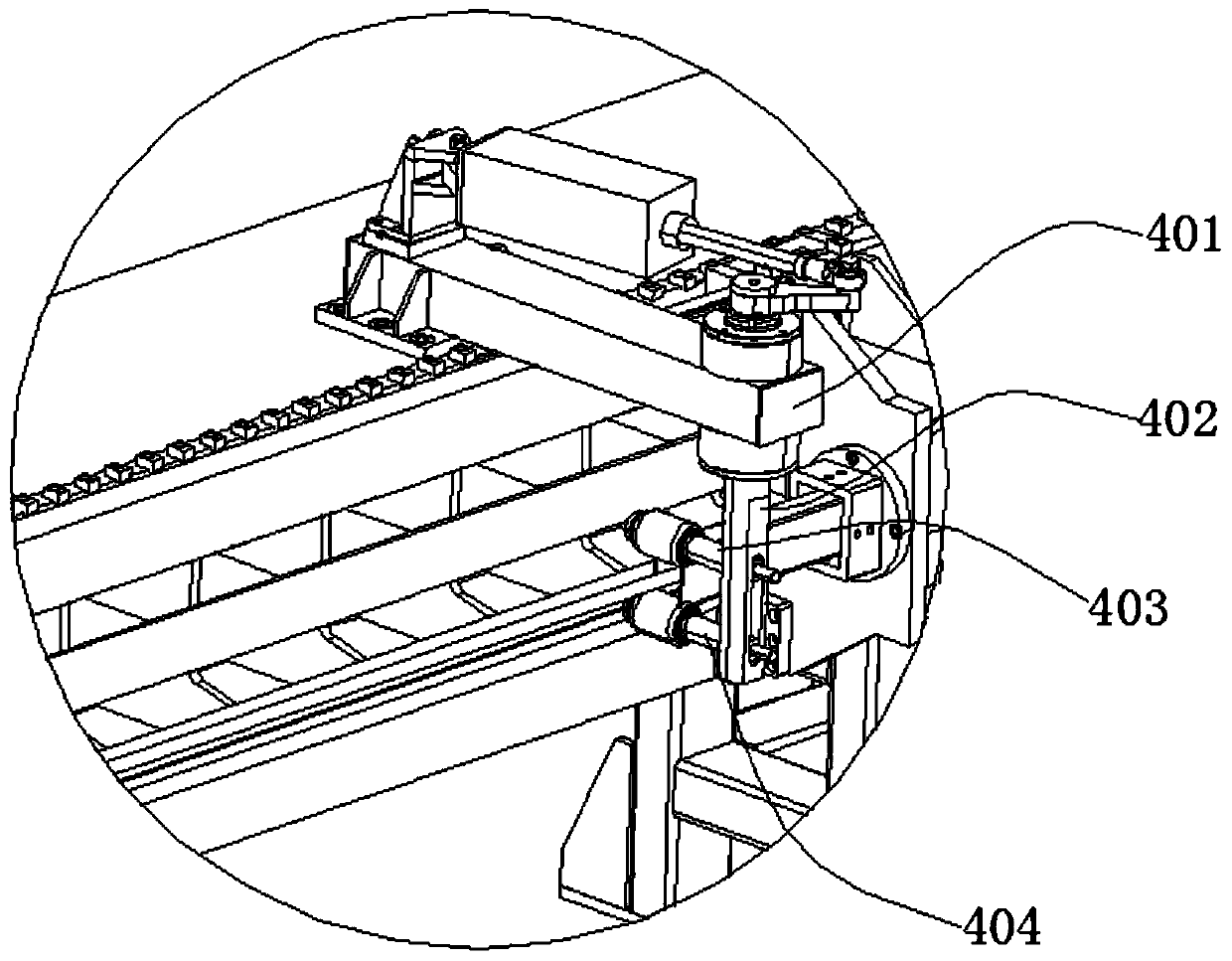
[0058] With embodiment 1, difference is: as figure 2 As shown, the auxiliary device 4 is also included, the auxiliary device 4 includes a support base 401, a vertical bar 402, an upper auxiliary bar 403 and a lower auxiliary bar 404, the support base 401 is fixed on the top of the frame 1, and the end extends out of the frame 1 the left side; the top of the vertical bar 402 is rotatably connected to the end of the support base 401, and the bottom is connected with the upper auxiliary bar 403 and the lower auxiliary bar 404; the upper auxiliary bar 403 and the lower auxiliary bar 404 are arranged in parallel, and the upper auxiliary bar 403 and the lower auxiliary bar 403 Auxiliary rod 404 is used to clamp the pipe. The top of the vertical bar 402 protrudes from the support base 401 and is connected with a cross bar. The support base 401 is provided with a driving device for pushing or pulling the other end of the cross bar. The auxiliary mechanism in this embodiment can cont...

Embodiment 3

[0061]Same as Embodiment 1, the difference is that the pipe bending device 2 includes a fixed seat 201, a pipe channel, a first fixed guide wheel 203, a first drive part 204, a second drive part 205, a second fixed guide wheel 207, a third Fixed guide wheel 208, first bending wheel 209, second bending wheel 210 and block 211; Fixed base 201 is installed on the side of frame 1 as the supporting platform of pipe bending device 2, and fixed base 201 comprises top cover and Bottom cover; the first fixed guide wheel 203, the pipe channel, the second fixed guide wheel 207, the third fixed guide wheel 208 and the stopper 211 are located between the top cover and the bottom cover, the first fixed guide wheel 203 and the second fixed guide wheel The wheel 207 is located on one side of the pipe passage, the third fixed guide wheel 208 and the stopper 211 are located on the other side of the pipe passage; the first bending wheel 209 is located at the outlet of the pipe passage, and the se...


PUM


Abstract

The invention discloses a pipe bending device and a use method for the same and belongs to the technical field of pipe bending machines. The pipe bending device comprises a rack, a fixation base, a pipe material channel, a fixation part, a first bending wheel and a second bending wheel, wherein the fixation base is installed on the side face of the rack; the fixation base comprises a top cover anda bottom cover; the fixation part is located between the top cover and the bottom cover; the fixation part is used to fix a pipe material and the pipe material channel is a channel disposed in the fixation part; the first bending wheel is located at an exit of the pipe material channel, and the second bending wheel is located on the side remote from the rack and inclined to a material ejection mechanism; and the first bending wheel is used to bend the pipe material horizontally and the second bending wheel is used to bend the pipe material vertically. The pipe bending device disclosed by theinvention has the advantages that bending can be realized on an X axis and a Z axis simultaneously; and processing accuracy is increased. In addition, the invention discloses the use method for the device. The method has the advantages that operations are simple; reliability is high, etc.

Description

[0001] The application number is: 201811438974.2, the application date is: November 28, 2018, and the name is: a divisional application of the invention patent application of a three-dimensional curvature pipe bender and its use method. technical field [0002] The invention belongs to the technical field of pipe bending machines, and in particular relates to a pipe bending device and a method for using the same. Background technique [0003] Pipe bending machines are generally divided into hydraulic pipe bending machines and CNC pipe bending machines. The hydraulic pipe bending machine is purely hydraulically driven, while the numerical control pipe bending machine is based on the hydraulic pipe bending machine. PLC control system is added to realize digital information control. The CNC three-dimensional pipe bending machine is mainly composed of three parts: mechanical part, hydraulic system and PLC control system. The mechanical part mainly includes feeding device, pipe be...

Claims


Application Information

Patent Timeline
Patent Type & Authority Applications(China)
IPC IPC(8): B21D9/10B21D43/02B21C51/00
CPCB21C51/00B21D9/00B21D43/02Y02P40/57
Inventor 吴善普吴善照
Owner ANHUI DEXI DHI TECH
Why Eureka
Try Eureka