Cooling system for electronic device

A technology for cooling systems and electronic equipment, which is applied to structural parts of electrical equipment, cooling/ventilation/heating renovation, circuits, etc., can solve problems such as leakage of synthetic oil, and achieve the effect of efficient absorption

Inactive Publication Date: 2018-04-17
EXASCALER
View PDF12 Cites 6 Cited by
  • Summary
  • Abstract
  • Description
  • Claims
  • Application Information

AI Technical Summary

Problems solved by technology

In addition, it has also been reported that the synthetic oil used corrodes the gaskets constituting the cooling system in a short period of time, causing leakage of the synthetic oil and hindering the operation.

Method used


Image

  • Cooling system for electronic device
  • Cooling system for electronic device
  • Cooling system for electronic device

Examples


Embodiment Construction

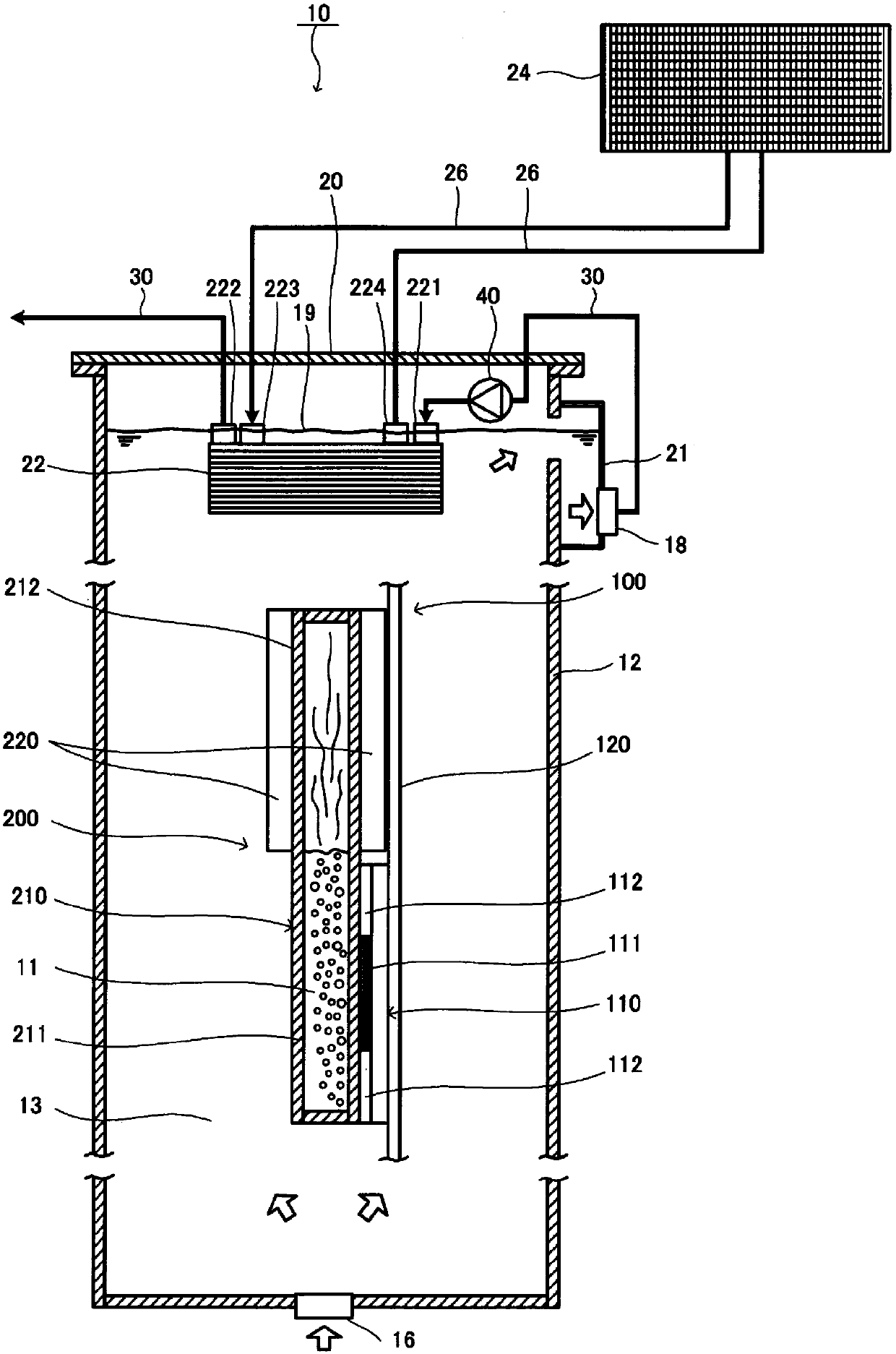
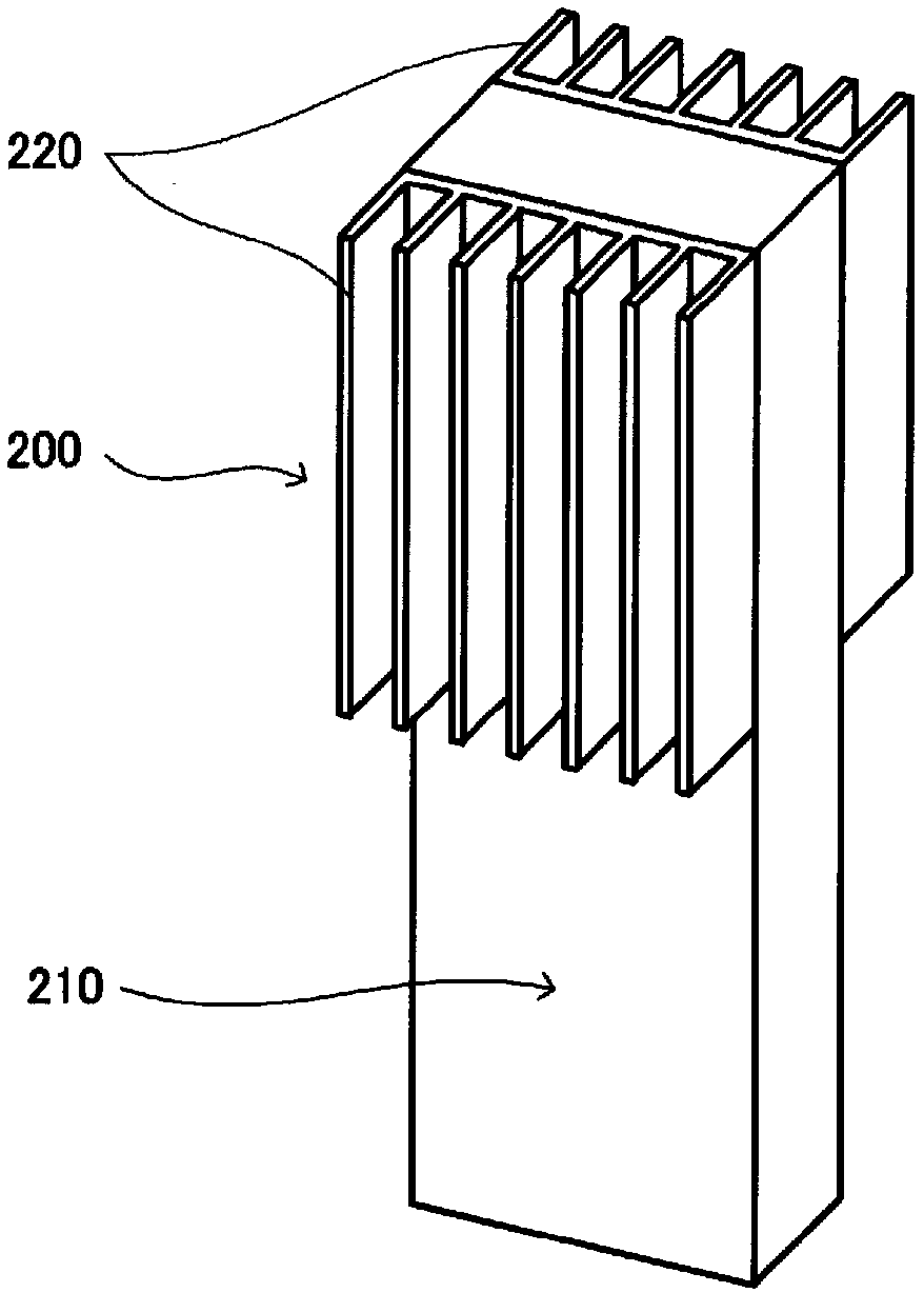
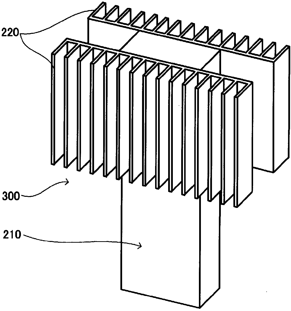
[0048] Hereinafter, preferred embodiments of the cooling system of the present invention will be described in detail based on the drawings. In the description of this embodiment, first, for a preferred embodiment, refer to figure 1 , Figure 2A , Figure 2B as well as Figure 2C The structure of the main part of the cooling system is explained as follows: a processor consisting of a bare chip (semiconductor chip) and a heat sink surrounding the bare chip is mounted on the board of the electronic device as a heat generating body, and the electronic device is housed in a cooling tank inside and allow to cool. Next, refer to image 3 as well as Figure 4 A preferred configuration example of the first heat exchanger will be described. Next, for a preferred embodiment, refer to Figure 5 , as an electronic device, only one unit including a board on which a plurality of processors is mounted is briefly shown, and the overall structure of a cooling system for accommodating and...


PUM


Abstract

A cooling system (10) has a cooling tank 12, a second cooling liquid (13) that has a boiling point T2 being placed inside an open space of the cooling tank (12). An electronic device (100) in which aprocessor (110) is mounted as a heat-emitting body on a board (120) is stored inside the open space of the cooling tank (12) and is immersed in the second cooling liquid (13) (boiling point T2). An ebullient cooling device (200) is thermally connected to the processor (110), a first cooling liquid (11) that has a boiling point T1 (where T1=T2 or T1<T2) being sealed in the ebullient cooling device(200). A first heat exchanger (22) is provided with: high-temperature-side flow channels for letting pass the second cooling liquid, the high-temperature-side flow channels comprising an aggregate ofnarrow gaps or minute flow channels; and low-temperature-side flow channels for letting pass a third cooling medium having a boiling point T3 (where T3=T2 or T3<T2), the low-temperature-side flow channels comprising an aggregate of narrow gaps or minute flow channels. The high-temperature-side flow channels and the low-temperature-side flow channels are provided alternately and are separated by walls. A pump (40) pressure-feeds the second cooling liquid (13), which is heated inside the cooling tank (12), toward the inlet to the high-temperature-side flow channels of the first heat exchanger (22).

Description

technical field [0001] The present invention relates to a cooling system for electronic equipment, and more particularly to a cooling system for electronic equipment for efficiently cooling electronic equipment such as supercomputers and data centers that require ultra-high performance and stable operation and that generate a large amount of heat from the electronic equipment itself . Background technique [0002] In recent years, one of the biggest issues determining the limit of the performance of supercomputers is power consumption, and the importance of research on power saving performance of supercomputers has been known to the general public. That is, the speed performance per unit power consumption (Flops / W) becomes an index for evaluating a supercomputer. In addition, in data centers, about 45% of the power consumption of the entire data center is used for cooling, and there are increasing demands for reducing power consumption by improving cooling efficiency. [0...

Claims


Application Information

Patent Timeline
Patent Type & Authority Applications(China)
IPC IPC(8): H01L23/473G06F1/20H05K7/20
CPCG06F1/20H01L23/473H05K7/20G06F1/206G06F2200/201H05K7/20236H05K7/20254H05K7/20263H05K7/20272H05K7/203H05K7/20327H05K7/20381H05K7/20763H05K7/20781H05K7/208H05K7/20818
Inventor 稻叶贤一齐藤元章
Owner EXASCALER
Why Eureka
Try Eureka