
Stirring feeder

A technology of mixing motor and mixing box, which is applied in mixers with rotating mixing devices, animal feeding devices, mixers, etc., can solve the problem of small contact area between blades and materials, wear of intermediate auger blades, and large coarse feed chopped particle size. and other problems, to achieve the effect of improving the kneading and cutting efficiency, slowing down the conveying capacity, and increasing the probability of contact

Pending Publication Date: 2018-04-20
SHIHEZI UNIVERSITY
View PDF0 Cites 1 Cited by
  • Summary
  • Abstract
  • Description
  • Claims
  • Application Information

AI Technical Summary

Problems solved by technology

[0003] First, the continuous screw auger is adopted, and its conveying capacity is much greater than the crushing capacity, resulting in large coarse feed particle size, long processing time and high power consumption;
[0004] Second, the opposite spiral auger pushes the material to the middle, causing the auger blades at both ends to rotate idly, insufficient kneading and cutting, and the middle auger blade wears seriously;
[0005] Third, the contact area between the blade and the material is small, and the processing efficiency is low

Method used


Image

  • Stirring feeder
  • Stirring feeder
  • Stirring feeder

Examples


Embodiment 1

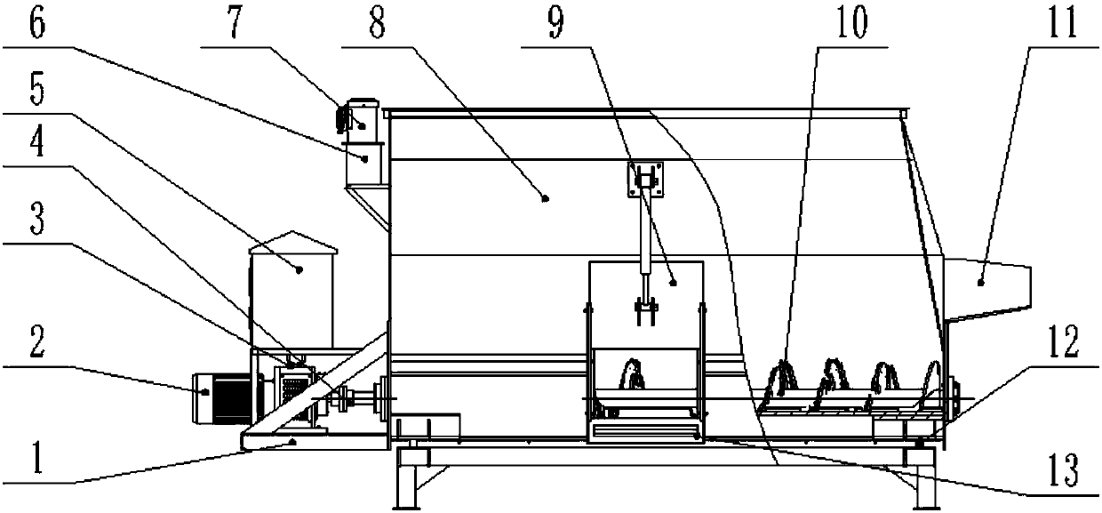
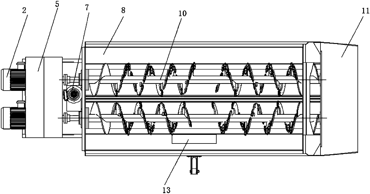
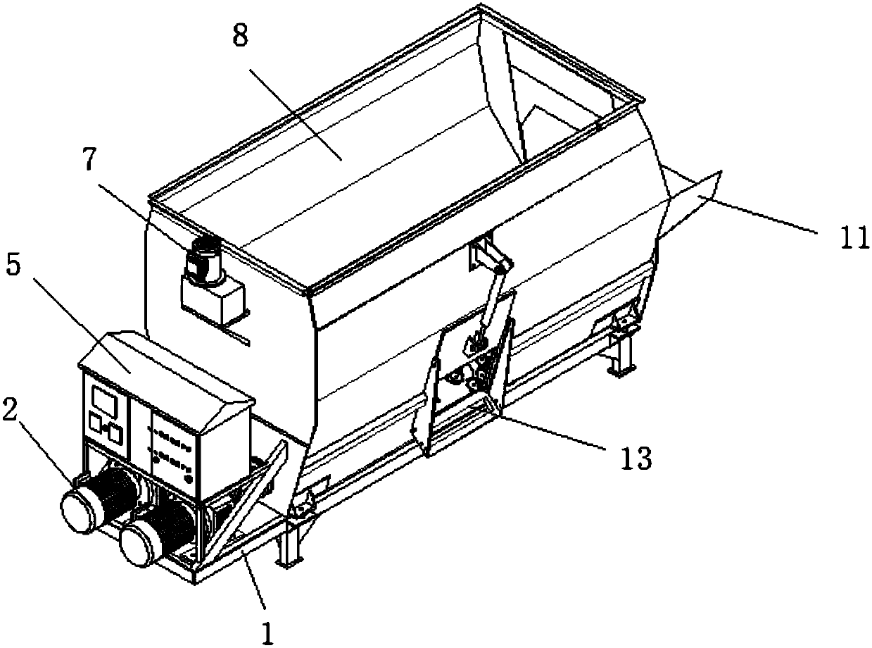
[0029] Such as figure 1 As shown, a stirring feeding machine of the present invention includes a stirring box 8, a segmented auger 10 and a driving mechanism; two parallel segmented augers 10 are horizontally arranged in the mixing box 8 and driven by the driving mechanism.

[0030] The mixing box 8 is in a horizontal cylindrical shape, and the mixing box 8 is provided with a feed inlet 11 on the side of the mixing box 8 .

[0031] The driving mechanism includes a stirring motor 2, a gearbox 3 and a coupling 4. The stirring motor 2 is fixedly connected to the outside of the stirring box 8 and is sequentially connected through the gearbox 3 and the coupling 4 to drive the segmented auger 10.

[0032] Stirring motor 2 is fixed by motor frame 1.

[0033] The segmented auger 10 is divided into a forward stirring section 101 and a reverse stirring section 104, and the forward stirring section 101 and the reverse stirring section 104 respectively have a number of spirally distribut...


PUM


Abstract

The invention relates to a stirring feeder, and belongs to the field of feed crushing mechanisms. The stirring feeder comprises a stirring box, a sectional auger and a driving mechanism. The sectionalauger is horizontally arranged in the stirring box, driven by the driving mechanism and divided into a forward stirring section and a reverse stirring section, a plurality of spirally distributed stirring vanes are arranged on the forward stirring section and the reverse stirring section, at least one crushing blade is arranged on each stirring vane, and the forward stirring section and the reverse stirring section are coaxial and opposite in spiral direction. The conveying capacity of the auger is reduced, the crushing capacity of the auger is improved, processing efficiency is improved, theproblem of serious abrasion of a middle auger due to idling of two ends of the auger is avoided, crushed coarse fodder and concentrated fodder are collected and sufficiently mixed and stirred under pushing of the opposite spiral vanes, the contact probability of the blades and materials is increased by the structural form, material rolling and cutting efficiency is improved, material conveying capacity is reduced, the materials sufficiently contact with the blades, and material processing efficiency is improved.

Description

technical field [0001] The invention relates to a stirring feeding machine, which belongs to the field of feed crushing mechanisms. Background technique [0002] The national grass-fed animal husbandry development plan, in order to ensure the health of cattle, sheep and other ruminants, improve feed utilization and breeding benefits, all pastures are now promoting the application of advanced full mixed ration feeding technology. According to the nutritional needs of ruminant animals, mix fine roughage and various additives in an appropriate proportion with a feeding machine, and then feed them ad libitum. Existing mixing method has following shortcoming: [0003] First, the continuous screw auger is adopted, and its conveying capacity is much greater than the crushing capacity, resulting in large coarse feed particle size, long processing time and high power consumption; [0004] Second, the opposite spiral auger pushes the material to the middle, causing the auger blades ...

Claims


Application Information

Patent Timeline
IPC IPC(8): A01K5/00B01F7/24
CPCA01K5/002B01F27/1144B01F27/2322B01F27/922
Inventor 温宝琴坎杂李景彬蒙贺伟戚江涛马朋勃王涛邹士杰罗鑫
Owner SHIHEZI UNIVERSITY
Learn More