
Takeoff and landing method of aircraft in aircraft carrier and device thereof

A technology for landing gear and aircraft, applied in aircraft parts, ground equipment, aircraft control, etc., can solve the problems of not being able to save deck layout area, not being able to take off with heavy loads, and high structural requirements, so as to achieve low aircraft structure requirements and save hull decks panel, pilot comfort effect

Inactive Publication Date: 2018-04-20
杨富云
View PDF6 Cites 1 Cited by
  • Summary
  • Abstract
  • Description
  • Claims
  • Application Information

AI Technical Summary

Problems solved by technology

This technology also has disadvantages, such as high-power electromagnetic motors will interfere with shipboard electronic devices, and the equipment is expensive
[0005] The third technical solution is Russia’s ski-jump take-off, that is, it flies out on the curved and tilted deck by the power of the aircraft. When the bomb is full, it cannot be filled with oil, and when it is full of oil, it cannot be filled with bombs.
Its disadvantage is that the aircraft decelerates too quickly, which requires high requirements for the pilot and aircraft structure, and it is separated from the aircraft take-off in two lanes, which cannot save the deck layout area.

Method used


Image

  • Takeoff and landing method of aircraft in aircraft carrier and device thereof
  • Takeoff and landing method of aircraft in aircraft carrier and device thereof
  • Takeoff and landing method of aircraft in aircraft carrier and device thereof

Examples


Embodiment Construction

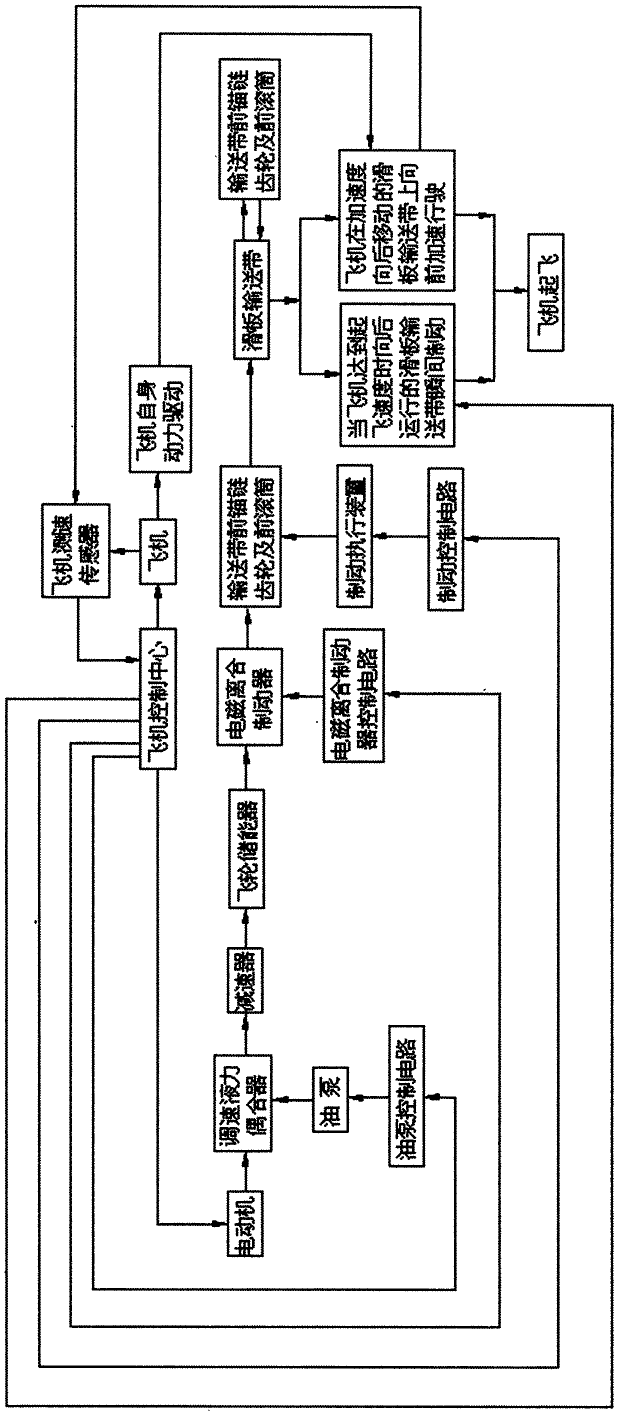
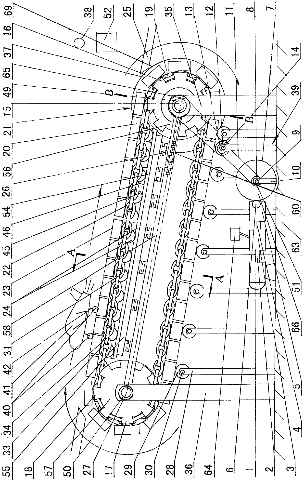
[0090] figure 1 Among them, the aircraft 41 is parked on the outer surface of the slide conveyor belt with a high front and a low slope at one end of the rear roller 56, that is, the rearmost end of the delivery runway 23. The inclination angle of the slide conveyor belt outer surface 23 is 0-30°, preferably 10°. ° left and right, aircraft 41 is ready to take off, and when aircraft control center 52 sends take-off command, aircraft 41 starts, and slides forward on the slide conveyor belt surface, promptly conveys runway 23; Control center 52; Aircraft control center 52 connects the power supply of motor 1 according to the requirement of aircraft 41 take-off, and motor 1 starts; The acceleration of the aircraft 41 on the measured slide conveyor belt 21 a2 When , the output signal instructs the oil pump 64 to control the circuit to increase the fuel supply of the oil pump 64 and increase the speed of the output shaft 4 of the speed-regulating hydraulic coupling. Its S is the set...


PUM


Abstract

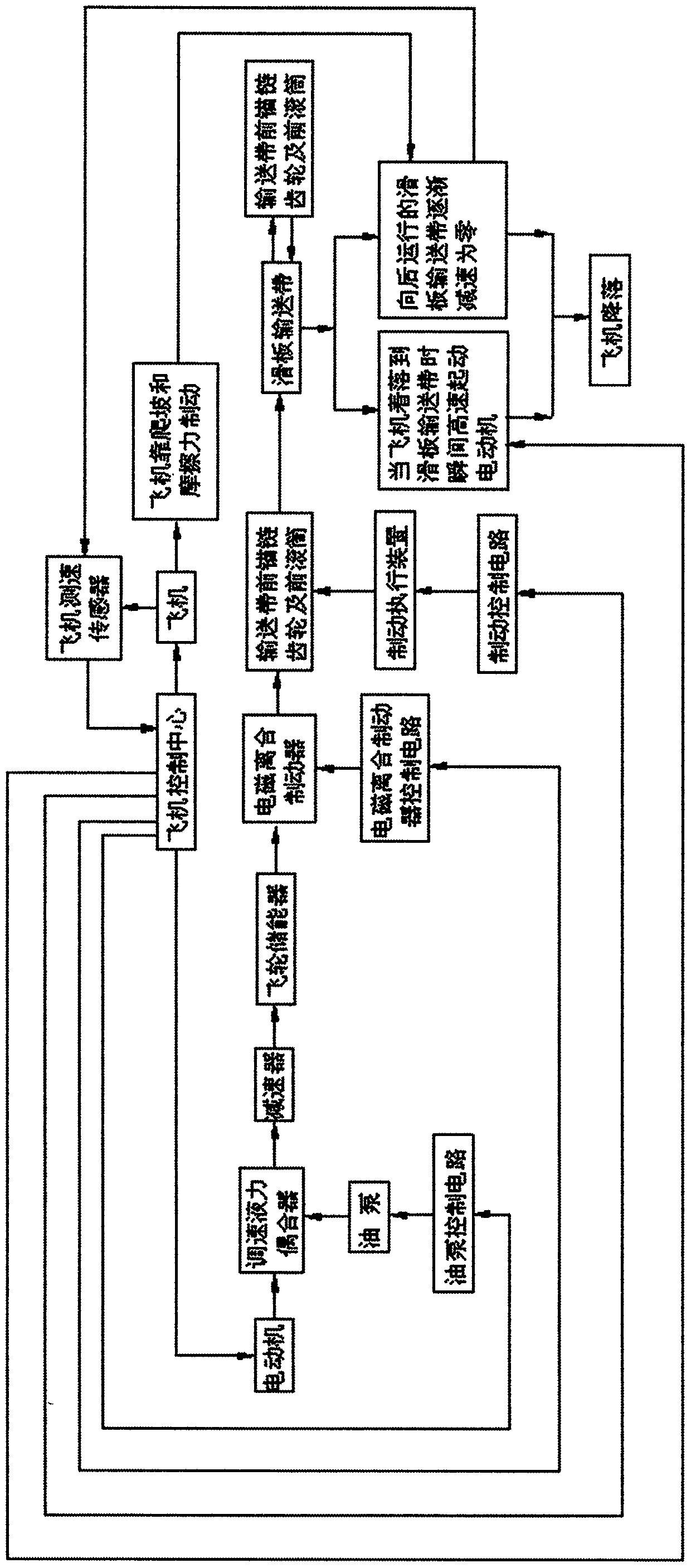
The invention discloses a takeoff and landing method of an aircraft in an aircraft carrier and a device thereof. In the takeoff process, by utilizing driving power of the aircraft (41), the aircraft gradually accelerates and coasts in a backward inclined slide conveyor belt (21) with low front and high rear; when takeoff speed is reached, the slide conveyor belt is suddenly braked to make the speed reach zero, then the aircraft slides off the runway and leaves the aircraft carrier to take off. In the landing process, the aircraft lands on the slide conveyor belt which rapidly moves backward, then the aircraft is braked to gradually decelerate and stays at the end of the slide conveyor belt. A motor drives a speed control hydraulic coupler to slow down through a reducer, drives fly wheels to store energy, and drives the closed loop slide conveyor belt to move backward through anchor chain gears connected with or disconnected with a rear drum by an electromagnetic clutch brake; the two sides are provided with a left chain (31) traction and a right chain (32) traction, a transportation runway (23) is composed of a horizontal bar (20), and a steel ball matrix slide plate (24) or an idler (64) is arranged under the slide conveyor belt, so that length of the runway is greatly shortened. The motor driving speed control hydraulic coupler has the advantages of low requirements for driving and aircraft, being easy to control, and achieving takeoff and landing of drones or heavy machines.

Description

technical field [0001] The invention relates to a method and a device for taking off and landing an aircraft of an aircraft carrier or an airport, in particular to a method and a device for shortening an aircraft runway. Background technique [0002] The runway on an aircraft carrier is only 200-300 meters long, and the runway on an airport is 2000-3000 meters long. The length of the runway is determined according to the requirements of the aircraft to take off and land. Taxiing on the runway accelerates, the runway is short, the aircraft cannot accelerate to the required speed for takeoff, and the aircraft cannot take off; the opposite is true for the landing of the aircraft, the aircraft needs to slow down on a certain length of runway, the runway is short, and the aircraft cannot stop taxiing at the end of the runway . [0003] Existing U.S. aircraft carriers generally use catapults to take off, such as electromagnetic catapults and steam catapults. Russian and Chinese a...

Claims


Application Information

Patent Timeline
Patent Type & Authority Applications(China)
IPC IPC(8): B64F1/00B64C19/00
CPCB64F1/00B64C19/00
Inventor 杨富云
Owner 杨富云
Learn More