Optimal well-location deployment method and device aiming at small fault block reservoir

A technology for deploying devices and well positions, which is applied to wellbore/well components, earthwork drilling, and fluid production. The effect of overcoming poor convergence and improving oil recovery

Active Publication Date: 2018-04-20
中科数智能源科技(深圳)有限公司
View PDF7 Cites 9 Cited by
  • Summary
  • Abstract
  • Description
  • Claims
  • Application Information

AI Technical Summary

Problems solved by technology

The disadvantage of this method is that the designed well pattern can only be a strictly regular well pattern, but due to factors such as the complex plane geometry of the fault block and the small scale of the fault block, the regular well pattern cannot be the most suitable for fault block oil production. Well Pattern Types for Reservoir Development
Therefore, this method will inevitably fail to obtain the optimal well layout scheme.

Method used


Image

  • Optimal well-location deployment method and device aiming at small fault block reservoir
  • Optimal well-location deployment method and device aiming at small fault block reservoir
  • Optimal well-location deployment method and device aiming at small fault block reservoir

Examples


Embodiment 1

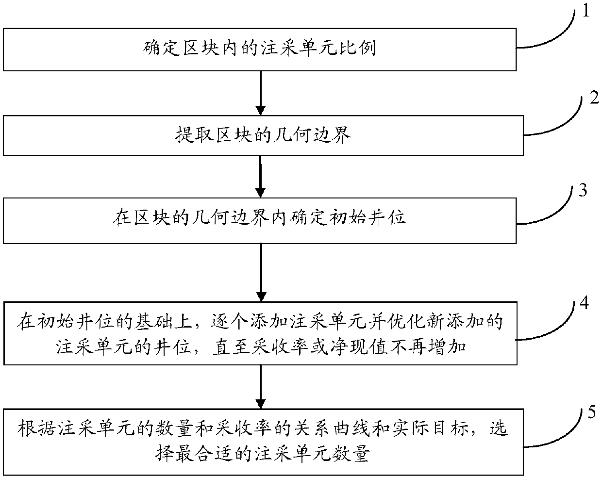
[0078] The present invention will be further described by taking block B of the F oilfield as an example. In this embodiment, the intelligent optimization method selects the particle swarm optimization algorithm, that is, the PSO algorithm. The objective function is to maximize the recovery rate, and the preset injection-production well number ratio is 1:2;

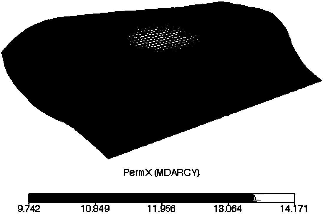
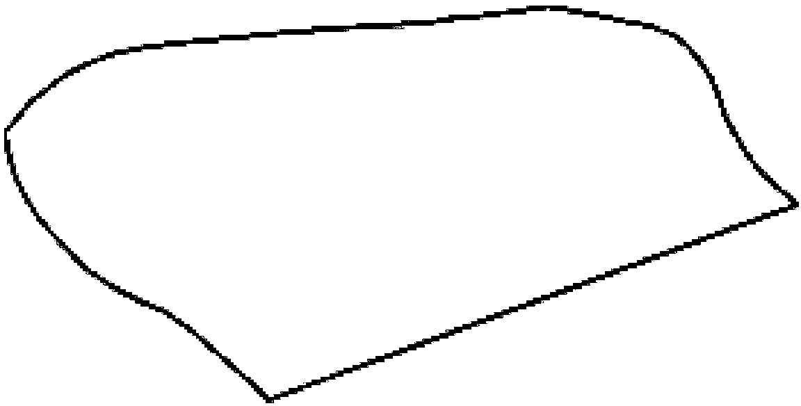
[0079] 1), extract the geometric boundary of the block, such as figure 2 As shown, the geometric boundary outside the reservoir is extracted from the reservoir geological model obtained by geological modeling, such as image 3 , pay attention to exclude the dead grid when extracting the boundary;

[0080] 2), determine the original well location. In this embodiment, there is no exploration well or drilled well in this block, because the original well location set is empty;

[0081] 3), adding injection-production units one by one, and optimizing the well positions of newly added injection-production units, such as Fi...


PUM


Abstract

The invention discloses an optimal well-location deployment method and device aiming at a small fault block reservoir, and belongs to the technical field of petroleum exploitation. The optimal well-location deployment method comprises the steps that 1, the proportion of injection-production units in a block is determined; 2, the geometric boundary of the block is extracted; 3, an initial well location is determined in the geometric boundary of the block; 4, on the basis of the initial well location, the injection-production units are added one by one, and the well locations of the newly-addedinjection-production units are optimized until the recovery ratio or the net present value is no longer increased; and 5, the most proper number of the injection-production units is selected accordingto the relation curve and the actual target between the number of the injection-production units and the recovery ratio. According to the optimal well-location deployment method and device, convergence is good, factors such as the plane geometric shape of a fault block, the size of the fault block, spatial distribution characteristics of an oil sand body, heterogeneity of a reservoir stratum, anddirectionality of the permeability are fully taken into account, and the recovery ratio or the net present value of the reservoir can be increased.

Description

technical field [0001] The invention relates to the technical field of petroleum exploitation, in particular to an optimal well location deployment method and device for small fault block oil reservoirs. Background technique [0002] Due to the division of fault blocks in complex fault-block reservoirs, the fault blocks are small and have different shapes, and each fault block is an independent development unit. Due to the small area of ​​fault blocks during development, it is difficult to deploy and produce wells with perfect conventional area well patterns, so small fault block reservoirs generally can only be developed with imperfect well patterns. [0003] In the process of well location deployment, it is necessary to design and adjust the well pattern structure to achieve the purpose of improving the recovery rate (or maximizing the net present value). For small fault block reservoirs, at present domestically, the automatic well location optimization method based on op...

Claims


Application Information

Patent Timeline
Patent Type & Authority Applications(China)
IPC IPC(8): E21B43/30E21B43/16
CPCE21B43/16E21B43/30
Inventor 龚斌刘玄李俊超
Owner 中科数智能源科技(深圳)有限公司
Why Eureka
Try Eureka