

Outer-level damping method of strap-down inertial navigation system based on adaptive complementation filtering
A technology of complementary filtering and strapdown inertial navigation, applied in the field of navigation strapdown inertial navigation, can solve the problems of sensitive covariance, inability to obtain accurate accelerometer error and gyro drift, and no basis for theoretical derivation, etc., to achieve high stability Effect
- Summary
- Abstract
- Description
- Claims
- Application Information
AI Technical Summary
Problems solved by technology
Method used
Image

Examples
Embodiment
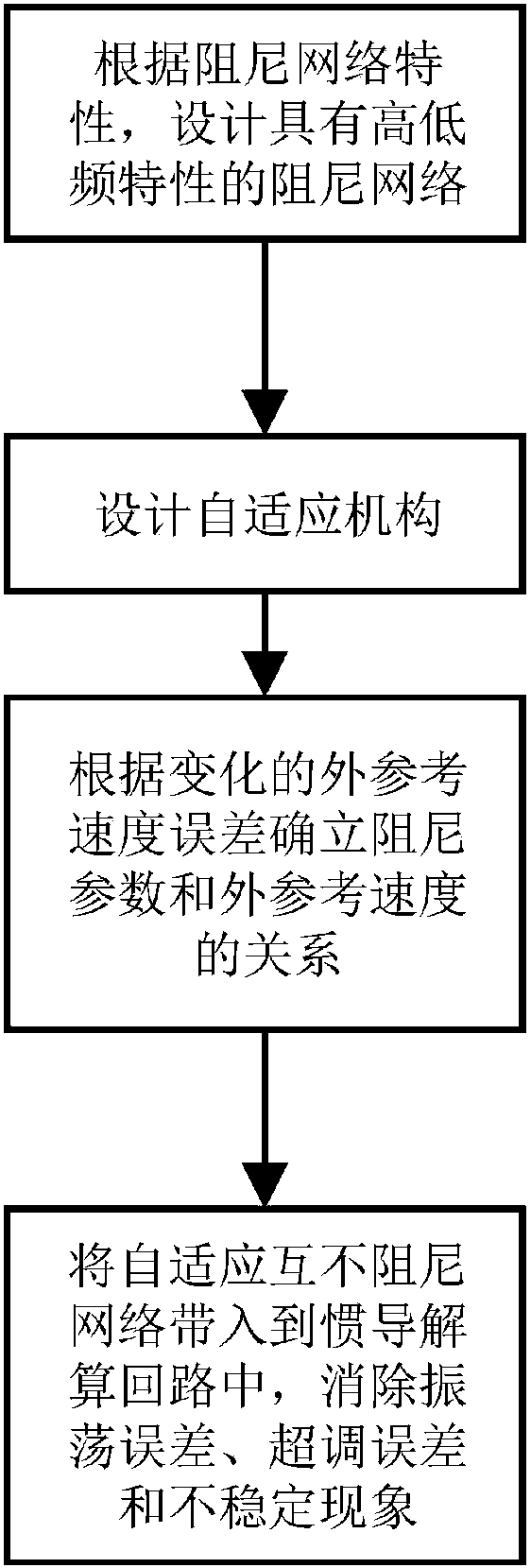
[0043] Embodiment: In the long-term navigation of ships, due to the existence of Schuler oscillation, the undamped inertial navigation system cannot meet the requirements, and the existence of gyro random drift will cause oscillation errors accumulated over time. The traditional external horizontal damping network can Eliminate the oscillatory error, but it will produce overshoot when the damping is switched, and the overshoot is proportional to the difference between the system speed and the external reference speed. The present invention selects the damping according to the external reference speed error that changes with time parameters to achieve higher stability, the implementation process is as attached figure 1 ,Specific steps are as follows:
[0044] Step 1: Analyze the amplitude-frequency characteristics of the constant-velocity network and the phase-lag-lead network, and perform complementary matching of the two networks;
[0045] as attached figure 2 Shown is the...
Embodiment 1
[0088] Embodiment 1: Set at 45.7796°N, 126.6705°E, the carrier running speed is 5m / s, the damping coefficient ξ is substituted into the damping network, η=μ=0.5, and the simulation parameter settings are shown in Table 3.
[0089] Set the external reference speed error according to the following formula, the simulation is as attached Figure 5 Shown:
[0090]
[0091] Since the working mode of the ship is related to the accuracy of the external reference speed, when the external reference speed is inaccurate, only the undamped state is performed. Select the external reference speed error according to the above formula, at t=5h, switch from the non-damping state to the damping state; at t=12h, switch from the damping state back to the non-damping state; Since the speed errors of the inertial navigation system at different time points are different, in order to verify the algorithm, the damping switching process at different time points is realized, and the simulation is car...
Embodiment 2
[0093] In order to verify that the adaptive network based on complementary filtering has engineering applicability, connect PHINS with H / H HZ001 inertial navigation system, use PHINS as a reference, and conduct experiments at a certain location (45.7796°N, 126.6705°E), the initial pitch angle , the roll angle and heading angle are -0.016°, -0.398°, 253.11° respectively, the damping coefficient ξ is substituted, and the Doppler external reference velocity error is as follows:
[0094] δv r =0.5×sin(2πt / 18h)kn
[0095] The constant value drift and noise of the gyroscope and accelerometer are shown in Table 3. The experimental data is analyzed and processed offline, and the state transition is performed at 1 hour to obtain the experimental results. The speed error and attitude angle error are shown in the attached Figure 8 and 9 shown.
[0096] Implementation Effect:
[0097] Embodiment A kind of simulation data verifies the feasibility of the fitting curve, and the speed er...
PUM
 Abstract
Description
Claims
Application Information