Coaxial transit time oscillator electron collector capable of working in long-pulse state

An electron collection and transit time technology, applied in the collector of transit time type electron tubes, etc., can solve the problems of reducing current density, less research, affecting microwave output, etc., to reduce current density, reduce energy deposition, and reduce operating frequency. pure effect

Inactive Publication Date: 2018-04-20
NAT UNIV OF DEFENSE TECH
View PDF6 Cites 6 Cited by
  • Summary
  • Abstract
  • Description
  • Claims
  • Application Information

AI Technical Summary

Problems solved by technology

However, in the experiment, it was found that a large amount of dust still filled the extraction cavity of the microwave source device, and the microwave still appeared the phenomenon of early cut-off
[0006] It can be seen from the above that although the collector with a slope can reduce the current density, since the electron absorption surface is obliquely downward, there will still be reflections, scattered electrons and secondary emitted electrons returning to the beam-wave interaction area, affecting microwave output
At present, there are few studies on how to use the electron collector structure to reduce electron reflection, scattering and secondary electron emission to interfere with the microwave output structure, especially the structure that can simultaneously reduce the current density and electron scattering reflection can be used for Ku-band transit time There is no public report on the technical scheme of the electron collector of the oscillator

Method used


Image

  • Coaxial transit time oscillator electron collector capable of working in long-pulse state
  • Coaxial transit time oscillator electron collector capable of working in long-pulse state
  • Coaxial transit time oscillator electron collector capable of working in long-pulse state

Examples


Embodiment Construction

[0028] The accompanying drawings constituting a part of this application are used to provide a further understanding of the present invention, and the schematic embodiments of the present invention and their descriptions are used to explain the present invention and do not constitute improper limitations to the present invention;

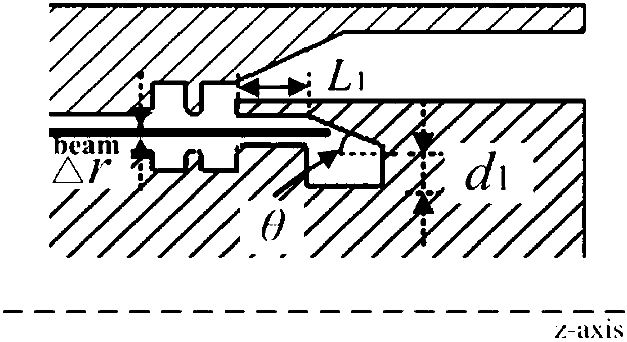
[0029] figure 1 It is a schematic diagram of the electron collector of the Ku-band coaxial transit time oscillator disclosed in prior art 1. Electrons move horizontally under the confinement of the magnetic field and are collected on the surface of the electron collector that is inclined downward. Although this collector adopts an inclined surface to increase the contact area between the electron beam and the collecting surface, which is beneficial to reduce the electron current density, it is still There will be a large number of scattered, reflected electrons, and the secondary emitted electrons return to the beam-wave interaction area to affect ...


PUM


Abstract

The invention relates to a coaxial transit time oscillator electron collector capable of working in a long-pulse state. The coaxial transit time oscillator electron collector is characterized in thatmagnetic induction lines on the edge of a magnetic field of a solenoid bend obliquely upwards, and an electron collection surface is of an obliquely-upward electron collector structure, so that the current density at a collection position is lowered; energy deposit is reduced; and reflected and scattered electrons are reduced. Generated plasma and secondary electrons return to a beam wave interaction area, so that microwave output is prevented from being influenced.

Description

technical field [0001] The invention relates to a microwave source device in the technical field of high-power microwaves, which is an electron collector that can be used in Ku-band transit time oscillators and is beneficial to increase microwave pulse width, and belongs to the technical field of high-power microwaves. Background technique [0002] The application background of the present invention is a high-power microwave source with repeated frequency operation. The high-power microwave source is a device that uses the interaction mechanism between the high-current relativistic electron beam and the eigenmode of the high-frequency structure in the vacuum high-frequency structure, and converts the energy of the high-energy electron beam into high-frequency electromagnetic wave energy. It is used in military and industrial applications. have important applications. At present, the energy efficiency of high-power microwave devices is generally low. The high-current relativ...

Claims


Application Information

Patent Timeline
Patent Type & Authority Applications(China)
IPC IPC(8): H01J23/027
CPCH01J23/027
Inventor 令钧溥徐伟力贺军涛宋莉莉高铭昊
Owner NAT UNIV OF DEFENSE TECH
Why Eureka
Try Eureka