High-strength PMSM (permanent magnet synchronous motor) rotor

A permanent magnet synchronous motor, high-strength technology, applied in the direction of synchronous machine parts, magnetic circuit rotating parts, magnetic circuit shape/style/structure, etc., can solve the problem of weakening electromagnetic performance, increasing motor air gap, and magnetic steel leakage Magnetic increase and other problems, to overcome the contradiction between structural strength and electromagnetic properties, increase structural strength, and avoid fracture phenomenon

Pending Publication Date: 2018-04-20
上海联孚新能源科技集团有限公司
View PDF0 Cites 1 Cited by
  • Summary
  • Abstract
  • Description
  • Claims
  • Application Information

AI Technical Summary

Problems solved by technology

[0006] (1) Set the rotor punching plate with a wider magnetic isolation bridge, which will lead to a significant increase in the magnetic flux leakage of the magnetic steel, resulting in weakened electromagnetic performance
Although the speed is increased, the torque is significantly reduced
[0007] (2) Put a layer of ultra-thin titanium alloy, carbon fiber and other high-strength non-magnetic sheath on the surface of the rotor. This method is not only complicated in process, but also needs to increase the air gap of the motor, which will inevitably lead to weakened electromagnetic performance.

Method used


Image

  • High-strength PMSM (permanent magnet synchronous motor) rotor
  • High-strength PMSM (permanent magnet synchronous motor) rotor
  • High-strength PMSM (permanent magnet synchronous motor) rotor

Examples


Embodiment 1

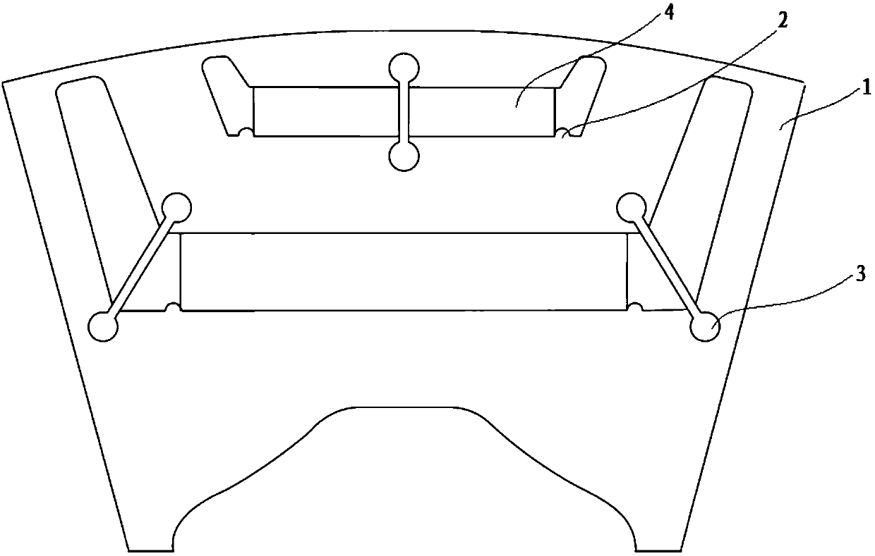
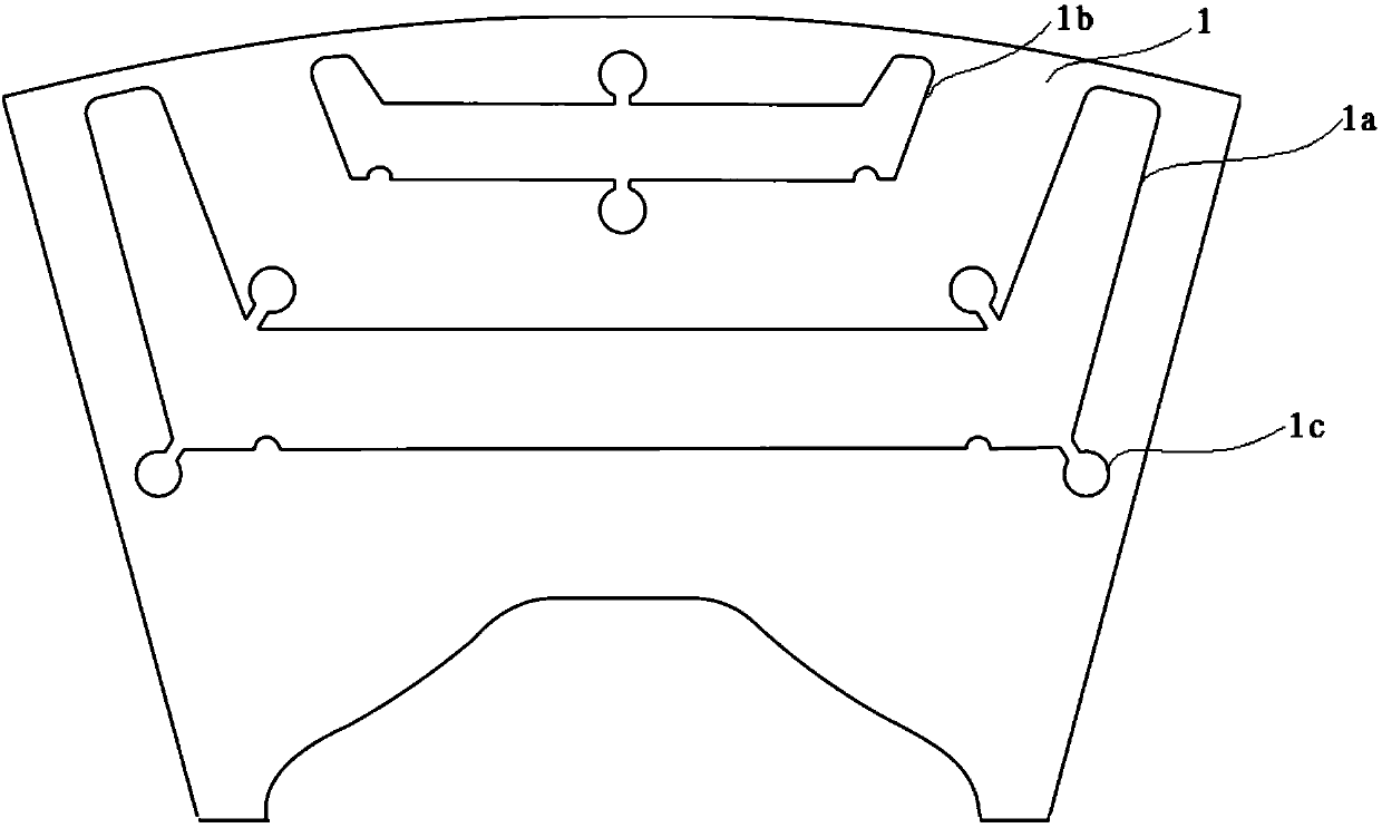
[0034] Such as figure 1 and figure 2 As shown, Embodiment 1 discloses a high-strength permanent magnet synchronous motor rotor, including: a rotor punch 1, the rotor punch 1 is in the shape of a circular sheet, and along the circumferential direction of the rotor punch 1, there are 8 sets of U Each group of U-shaped magnetic steel grooves includes two U-shaped magnetic steel grooves arranged along the radial direction of the rotor punching plate 1, which are respectively the first U-shaped magnetic steel groove 1a and the second U-shaped magnetic steel groove The U-shaped magnetic steel groove 1b, the first U-shaped magnetic steel groove 1a and the second U-shaped magnetic steel groove 1b are all symmetrical about the same radial direction of the rotor punch 1, and the U-shaped magnetic steel groove near the center of the rotor punch 1 is the first U-shaped magnetic steel groove. A U-shaped magnetic steel groove 1a, the U-shaped magnetic steel groove away from the center of ...

Embodiment 2

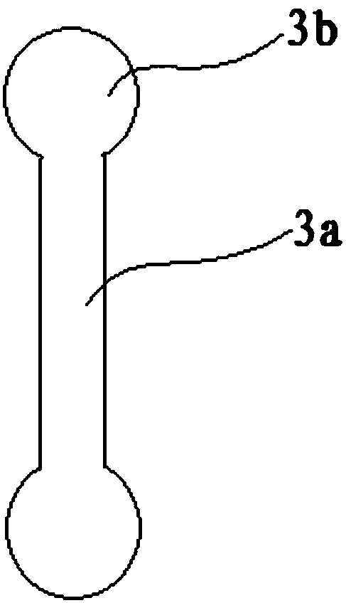
[0044] Such as figure 1 Shown, embodiment 2 is on the basis of embodiment 1, and the middle position of the second U-shaped magnetic steel groove 1b of embodiment 2 is also provided with the non-magnetic conduction across the groove width direction of the second U-shaped magnetic steel groove 1b Connecting piece 3, the connection method between the non-magnetic connecting piece 3 arranged at the second U-shaped magnetic steel slot 1b and the rotor punch 1 is the same as that of the non-magnetically conductive connecting piece at the first U-shaped magnetic steel slot 1a in Example 1 3 are connected in the same way, and the axis of the non-magnetic connecting piece 3 passes through the center of the rotor punching piece 1. And the non-magnetic connecting piece 3 in this embodiment is made of austenitic stainless steel.

[0045] In other embodiments, the non-magnetic connecting piece 3 is not limited to the location of the above embodiments 1 and 2, and can also be arranged at ...


PUM


Abstract

The invention discloses a high-strength PMSM (permanent magnet synchronous motor) rotor, and the rotor comprises a rotor punching sheet, wherein a plurality of U-shaped magnetic steel groove groups are arranged in the peripheral direction of the rotor punching sheet. Each U-shaped magnetic steel groove group comprises at least two U-shaped magnetic steel grooves which are arranged in the radial direction of the rotor punching sheet, wherein the U-shaped opening of each U-shaped magnetic steel groove backs on to the center of the rotor punching sheet. The rotor also comprises a magnetic non-conductive connecting part which is across the U-shaped magnetic steel grooves in the width direction of the U-shaped magnetic steel grooves, wherein the strength of the magnetic non-conductive connecting part is greater than the strength of the rotor punching sheet; and magnetic steels which are disposed in the U-shaped magnetic steel grooves. The setting of the magnetic non-conductive connecting part at the U-shaped magnetic steel grooves improves the structural strength of the rotor punching sheet at a magnetic bridge. When the rotor punching sheet rotates, the magnetic non-conductive connecting part can counteract a part of an inertia force, protects the rotor punching sheet from being broken at the magnetic bridge, cannot enable the magnetic leakage to be worse, and overcomes the conflict between the structural strength of the rotor punching sheet and the electromagnetic performances in the prior art.

Description

technical field [0001] The invention relates to the field of permanent magnet motor rotor structure design, in particular to a high-strength permanent magnet synchronous motor rotor. Background technique [0002] With the increasingly serious environmental pollution and energy crisis, artificial intelligence and automatic driving are becoming more and more mature. The country is vigorously advocating new energy electric smart vehicles. Major companies at home and abroad have entered the field and developed various new energy electric vehicles. . [0003] Permanent magnet synchronous motor is the mainstream motor used in electric vehicles. Permanent magnet synchronous motor has the advantages of simple structure, small size, low loss, high efficiency and easy control. [0004] At present, the permanent magnet synchronous motor is developing towards the direction of permanent magnetization, high speed and integration. However, with the continuous increase of the speed of the ...

Claims


Application Information

Patent Timeline
IPC IPC(8): H02K1/27H02K1/30H02K21/02
CPCH02K1/27H02K1/30H02K21/02
Inventor 李孟德张根发高梯学韩新江张伟
Owner 上海联孚新能源科技集团有限公司
Why Eureka
Try Eureka