Starter generator

A technology for starting generators and power generation components, which is applied to electrical components, electromechanical devices, electric components, etc., can solve the problems of large starting energy consumption, small central shaft mass, and low rotational inertia of generators, and achieves reduction of starting energy consumption, The effect of stable rotation and increased power generation

Pending Publication Date: 2018-04-20
浙江力俭新能源科技有限公司
View PDF0 Cites 3 Cited by
  • Summary
  • Abstract
  • Description
  • Claims
  • Application Information

AI Technical Summary

Problems solved by technology

[0002] Starter generators are widely used in the new energy electric vehicle industry, construction industry and other related industries. The current starter generators drive the central shaft to rotate through an external power source to cut the magnetic field lines for power generation. The power generation method of the outer stator and inner rotor is adopted. The diameter is small, the power generation efficiency of this power generation method is low, and because the mass of the central shaft is small, the rotational inertia is low, and the generator requires a large start-up energy consumption

Method used


Image

  • Starter generator
  • Starter generator
  • Starter generator

Examples


Embodiment 1

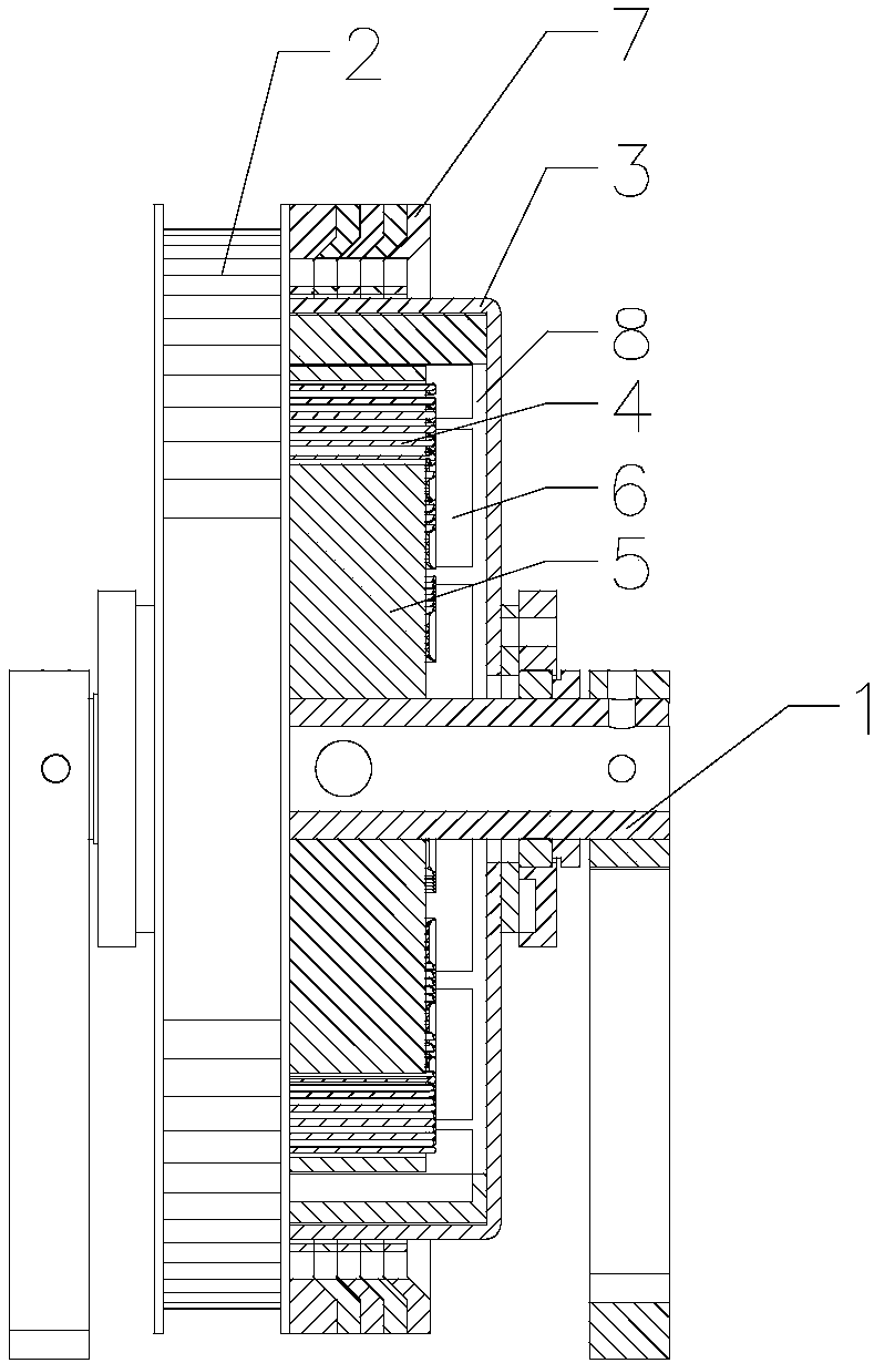
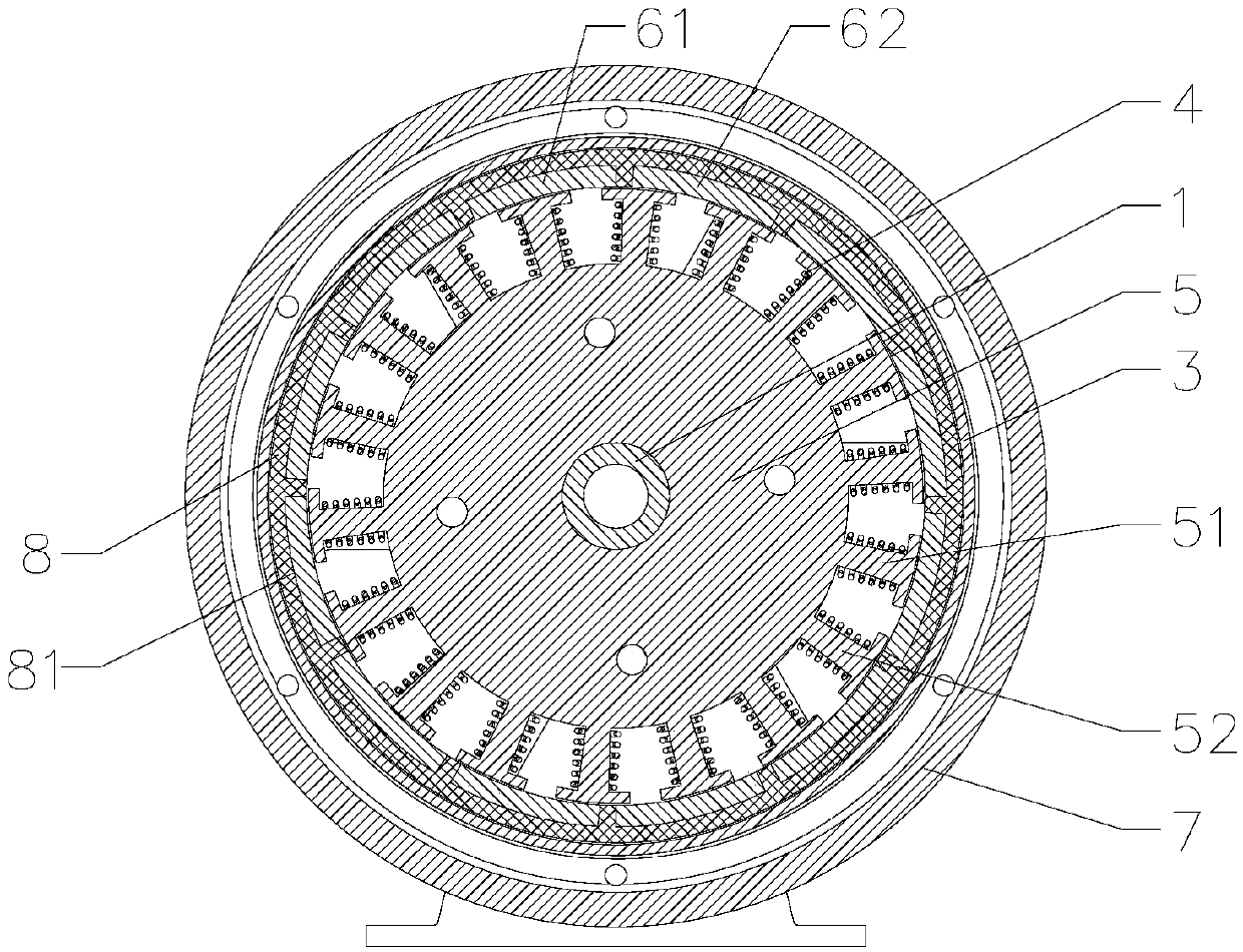
[0035] Such as Figures 1 to 3 As shown, the present invention provides a starter generator, including a fixed shaft 1, a transmission wheel 2 sleeved on the fixed shaft 1 and rotatably connected to the fixed shaft 1, and a housing 3 arranged on the transmission wheel 2. The transmission wheel 2 It is connected to the external power source by transmission, and the housing 3 is equipped with a power generation assembly. The power generation assembly includes an excitation coil 4 arranged on the fixed shaft 1 and a permanent magnet 6 arranged on the inner wall of the housing 3. The excitation coil is arranged on the fixed shaft 1 4. A permanent magnet 6 is set on the inner wall of the casing 3. Since the casing 3 is set on the transmission wheel 2, the permanent magnet 6 rotates together with the transmission wheel 2, thereby cutting the magnetic force line to generate power. Through the setting of the outer rotor inner stator, The rotor is fixed on the housing 3. The housing 3 ...

Embodiment 2

[0054] Such as Figure 4 As shown, the main difference between this embodiment and the first embodiment is that the casing 3 includes a first casing 31 and a second casing 32 .

[0055] The casing 3 includes a first casing 31 and a second casing 32, and the transmission wheel 2 is arranged between the first casing 31 and the second casing 32. The benefit of such an arrangement is that both ends of the transmission wheel 2 can be The power generation component is arranged so that the weights at both ends of the drive wheel 2 are more balanced, the use of the generator is more stable, and the power generation of the generator is increased, so that the power generation of the generator is more efficient.

Embodiment 3

[0057] Such as Figure 5 As shown, the main difference between the present embodiment and the first embodiment is that there are multiple power generating components arranged parallel and parallel inside the casing 3 along the axial direction of the casing 3 .

[0058] There are a plurality of power generating components arranged parallel to the inside of the housing 3 along the axial direction of the housing 3 . The advantage of such arrangement is that the power generation of the generator is increased and the power generation of the generator is more efficient. In this embodiment, there are two groups of power generation components, and the specific number can be selected according to the power generation capacity.

[0059] It can be understood that the power generation components can also be provided with 3 groups, 4 groups, 5 groups, 6 groups and so on.


PUM


Abstract

The invention provides a starter generator, which includes a fixed shaft, a transmission wheel sleeved on the fixed shaft and connected in rotation with the fixed shaft, and a casing arranged on the transmission wheel. There is a power generation component. The power generation component includes an excitation coil set on a fixed shaft and a permanent magnet set on the inner wall of the casing. Since the casing is set on the transmission wheel, the permanent magnet rotates with the transmission wheel to cut the magnetic force line to generate electricity. , through the setting of the outer rotor and the inner stator, the rotor is fixed on the casing, the casing not only plays a role of protection, but also increases the weight of the rotor to increase the rotational inertia of the rotor, so that the power generation can be reduced under the same output power The start-up energy consumption of the generator makes the start-up of the generator more economical and efficient. The outside of the housing is provided with a counterweight for increasing the rotational inertia of the housing, thereby making the start-up of the generator more economical and efficient.

Description

technical field [0001] The invention relates to a starter generator. Background technique [0002] Starter generators are widely used in the new energy electric vehicle industry, construction industry and other related industries. The current starter generators drive the central shaft to rotate through an external power source to cut the magnetic field lines for power generation. The power generation method of the outer stator and inner rotor is adopted. The diameter is small, the power generation efficiency of this power generation method is low, and because the mass of the central shaft is small, the rotational inertia is low, and the generator requires a large start-up energy consumption. Contents of the invention [0003] The object of the present invention is to provide a starter generator that can be started efficiently. [0004] In order to achieve the above object, the present invention adopts the following technical solutions: a starter generator, including a fix...

Claims


Application Information

Patent Timeline
Patent Type & Authority Applications(China)
IPC IPC(8): H02K7/18H02K21/22
CPCH02K7/1807H02K21/22
Inventor 汪力俭王溢
Owner 浙江力俭新能源科技有限公司
Why Eureka
Try Eureka