Supercharge Your Innovation With Domain-Expert AI Agents!

Motor rotor position correcting method, device and equipment thereof and storage medium

A technology of motor rotor and storage medium, which is used in the estimation/correction of motor parameters, control of electromechanical transmission devices, electronic commutators, etc. The effect of controlling performance

Active Publication Date: 2018-04-20
ZTE CORP
View PDF4 Cites 6 Cited by
  • Summary
  • Abstract
  • Description
  • Claims
  • Application Information

AI Technical Summary

Problems solved by technology

[0005] In view of this, the object of the present invention is to provide a motor rotor position correction method, device and equipment, and storage media to solve the interference problem existing in the control process of permanent magnet synchronous motors

Method used


Image

  • Motor rotor position correcting method, device and equipment thereof and storage medium
  • Motor rotor position correcting method, device and equipment thereof and storage medium
  • Motor rotor position correcting method, device and equipment thereof and storage medium

Examples


no. 1 example

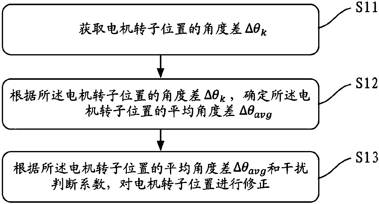
[0029] Such as figure 1 As shown, the first embodiment of the present invention provides a motor rotor position correction method, the method includes steps:

[0030] S11. Obtain the angle difference Δθ of the rotor position of the motor k .

[0031] As an example, by adding a resolver to the permanent magnet synchronous motor and adding a decoder circuit to detect the rotor position of the motor, if θ k Expressed as the angle of the current detected rotor position of the motor, θ k-1 Expressed as the angle of the motor rotor position detected last time, the angle difference Δθ of the motor rotor position k = θ k -θ k-1 . It should be noted that the time interval between the current detection and the last detection is not limited.

[0032] S12, according to the angle difference Δθ of the rotor position of the motor k , to determine the average angular difference Δθ of the rotor position of the motor avg .

[0033] In one embodiment, the angle difference Δθ according ...

no. 2 example

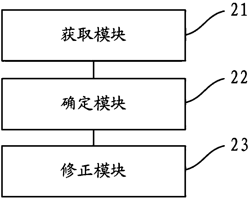
[0060] Such as figure 2 As shown, the second embodiment of the present invention provides a motor rotor position correction device, the device includes an acquisition module 21, a determination module 22 and a correction module 23;

[0061] The obtaining module 21 is used to obtain the angle difference Δθ of the rotor position of the motor k .

[0062] As an example, by adding a resolver to the permanent magnet synchronous motor and adding a decoder circuit to detect the rotor position of the motor, if θ k Expressed as the angle of the current detected rotor position of the motor, θ k-1 Expressed as the angle of the motor rotor position detected last time, the angle difference Δθ of the motor rotor position k = θ k -θ k-1 . It should be noted that the time interval between the current detection and the last detection is not limited.

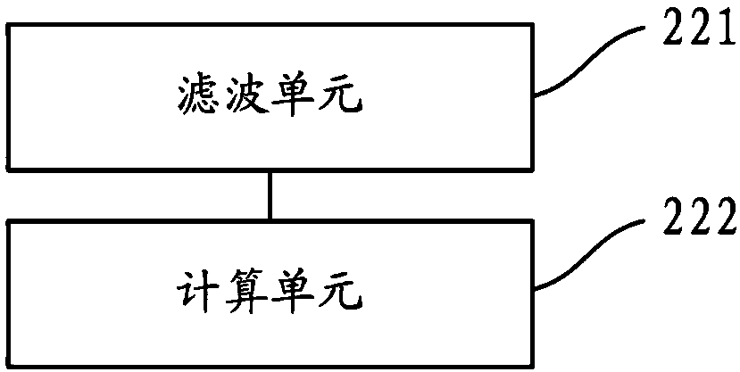
[0063] The determining module 22 is configured to use the angle difference Δθ according to the rotor position of the motor k , to deter...

no. 3 example

[0091] like Figure 5 As shown, the third embodiment of the present invention provides a motor rotor position correction device, which includes: a memory 31, a processor 32, and a motor rotor stored in the memory 31 and operable on the processor 32 A position correction program, when the motor rotor position correction program is executed by the processor 32, it is used to implement the following steps of the motor rotor position correction method:

[0092] Obtain the angle difference Δθ of the rotor position of the motor k ;

[0093] According to the angle difference Δθ of the rotor position of the motor k , to determine the average angular difference Δθ of the rotor position of the motor avg ;

[0094] According to the average angle difference Δθ of the rotor position of the motor avg and the interference judgment coefficient to correct the rotor position of the motor.

[0095] When the motor rotor position correction program is executed by the processor 32, it is also...


PUM


Abstract

The invention discloses a motor rotor position correcting method, a device and equipment thereof and a storage medium. The motor rotor position correcting method comprises the steps of acquiring an angle difference deltathetak of a motor rotor position; according to the angle difference deltathetak of the motor rotor position, determining an average angle difference deltathetaavg of the motor rotor position; and according to the average angle difference deltathetaavg and an interference determining coefficient of the motor rotor position, correcting the motor rotor position. According to the motor rotor position correcting method, the device and the equipment thereof and the storage medium, through performing interference degree determining on the angle difference of the motor rotor position and correcting the motor rotor position, the position information of the motor rotor can be more accurately acquired, thereby improving reliability and control performance.

Description

technical field [0001] The invention relates to the technical field of motor control, in particular to a motor rotor position correction method, device and equipment, and a storage medium. Background technique [0002] Compared with AC asynchronous motors, permanent magnet synchronous motors have many advantages such as simple structure and high efficiency, so they are widely used in new energy vehicles, wind power generation and other fields. The control methods of permanent magnet synchronous motors can be divided into two categories: position sensorless and position sensor. [0003] The position sensorless control method of the permanent magnet synchronous motor needs to establish an accurate model of the motor, and estimate the stator position and speed of the permanent magnet synchronous motor by detecting parameters such as the stator voltage and current of the motor. The quality of its control performance depends on the accuracy of the motor model. However, since the...

Claims


Application Information

Patent Timeline
Patent Type & Authority Applications(China)
IPC IPC(8): H02P6/16H02P21/18H02P23/14
CPCH02P6/16H02P21/18H02P23/14H02P2203/03
Inventor 陈景熙金帅刘辉
Owner ZTE CORP
Features
  • R&D
  • Intellectual Property
  • Life Sciences
  • Materials
  • Tech Scout
  • Unparalleled Data Quality
  • Higher Quality Content
  • 60% Fewer Hallucinations
Learn More